Body
Decorative/Protective Film
In this manual: Body
~2min read
Overview - Protective Films
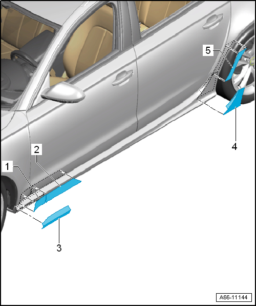
1 - Protective Foil - Fender
2 - Protective Foil - Door
3 - Protective Foil - Front Sill Panel Trim
4 - Protective Foil - Rear Sill Panel Trim
5 - Protective Foil - Side Panel Frame
Protective Film, Replacing
 Note
- Apply the protective foils as follows.
- The adhesive surfaces must free of dust and grease. Clean with for example Cleaning Solution -D 009 401 04-.
- Clean the surfaces on the body with a water/isopropyl mixture, (for example Cleaning Solution -009 401 04-) or with tap water and 2 or 3 drops of dish washer detergent.
- Peel off the backing and moisten the entire adhesive surface.
- Position the foil evenly and centered to the edges.
- Press on the foil from the center toward the wheels so that the water film under the foil gets pressed out.
- This prevents bubbles from forming.
- If there are any bubble, use a needle to piece them and let the air out.
Roof Bars/Roof Rails
 Caution
Use bolt locking fluid when installing the nuts.
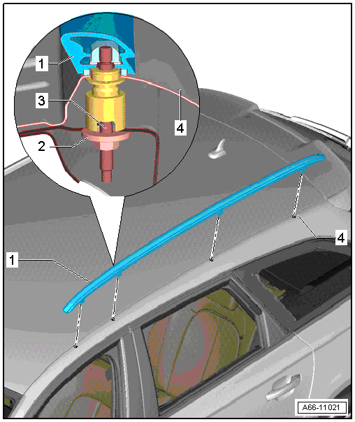
1 - Roof Railing
- Removing
- Lower the headliner. Refer to → Body Interior; Rep. Gr.70; Roof Trim Panels; Headliner, Removing and Installing.
- Loosen the head curtain airbag and move it to the side.
- Remove the nuts and then lift the roof railing off the roof.
- Installing
- Adjusting elements must be pushed into the roof and be in the installation position with slight pretension.
- Position the roof railing on the roof so the threaded pins go through the adjusters.
- Follow the installation sequence:
- Tighten both nuts on the inside first, and then tighten the nuts on the outside.
2 - Nut
- Tightening specification. Refer to → Chapter "Overview - Roof Railing".
3 - Adjusting Element
- Insert front adjusting element into hole provided and slide it to the rear into installation position.
- Insert the remaining adjusting elements into hole provided and slide forward into installation position.
- Position the adjusting elements so that they contact the outer panel with light pre-tension of 0,4 N·m.
4 - Roof
Was this page helpful?