Diagnosis and Testing - Wheels and Tires
Preliminary Inspection
- Confirm the customer concern by performing a road test on a smooth road. If any vibration is evident, refer to Symptom Chart: NVH.
- To maximize tire performance, inspect the tires for signs of incorrect inflation and uneven wear, which may indicate the need for balancing, rotation or front suspension adjustment.
- Correct tire pressure and driving technique have a major effect on tire life. Heavy cornering, excessive acceleration and unnecessary hard braking increase tire wear.
Tire replacement must be performed according to the recommendations for:
- tire size.
- speed rating.
- load range.
- Tire construction type.
Using tires/wheels of any other size, load range or type may seriously affect:
- ride.
- handling.
- speedometer/odometer calibration.
- vehicle ground clearance.
- tire-to-body and tire-to-chassis clearance.
- wheel hub bearing life.
- braking performance.
New wheels must be installed if the vehicle wheels are:
- bent.
- cracked.
- dented.
- severely corroded.
- leaking.
- have elongated wheel stud holes.
- have excessive lateral or radial runout.
It is essential to use only the tire sizes specified on the tire placard located on the driver door or door pillar of the vehicle. Larger or smaller tires may damage the vehicle, affect its durability and require speedometer calibration changes. Make sure the wheel size and offset match the original wheel specification for the tire being used.
Inspect the tires for signs of abnormal wear. Use the following descriptions to determine the wear type.
Check the tires for:
- cuts.
- stone bruises.
- scrapes.
- bulges.
- embedded objects.
Check the valve stems for:
- cracks.
- cuts.
Install a new valve stem if damage is found or when installing a new tire or wheel.
Tread Wear Indicators are molded into the bottom of the tread grooves. Replace the tire when the indicator bars become level with the tread surface, or when tread depth measures less than 1.6 mm (2/32 inch).
Tire Wear
Tire wear is usually defined as the loss of tread depth. Tread wear is caused by friction with the road surface. The tread should wear evenly around the entire circumference of the tire and across the entire tread surface. When this is not the case, the tire may show abnormal or irregular wear.
Normal Tire Wear
Normal tire wear is defined as even wear across and around the tread. Because many factors (driving style, road surface, vehicle type, tire type) can affect tire wear, there is no absolute expected mileage for normal wear. A tire is considered worn when the tread is worn down to the tread wear indicators.
Abnormal/Improper Tire Wear
Abnormal/improper tire wear is defined as tire wear that is not even across or around the tread, and which causes performance-related concerns.
Abnormal/improper wear may be caused by numerous factors, including driving style (aggressive, passive), climate (hot, cold), road conditions, loading, and vehicle maintenance (correct tire pressure, rotation intervals and balance). It is important to determine the root cause of the abnormal wear before performing a repair. Tires with abnormal/improper tire wear may be serviceable provided the minimum tread depth is more than 1.6 mm (2/32 in) and the tire does not cause vehicle performance concerns (noise/vibration).
Inner Edge/Shoulder Wear
Inner edge (or shoulder) wear occurs on the inner edge of the tire and is usually caused by excessive toe and/or excessive negative camber. If the outer shoulder tread depth is at least 50% greater than the inner shoulder tread depth, the tire has inner edge/shoulder wear. To determine if the tires have this type of wear, visually inspect the tires. In some cases, it may be necessary to measure the tread depth of each rib and compare it to the shoulder tread depth.
Outer Edge/Shoulder Wear
Outer edge (or shoulder) wear occurs on the outer edge of the tire and is usually caused by excessive toe and/or excessive positive camber. If the inner shoulder tread depth is at least 50% greater than the outer shoulder tread depth, the tire has outer edge/shoulder wear. To determine if the tires have this type of wear, visually inspect the tires. In some cases, it may be necessary to measure the tread depth of each rib and compare it to the shoulder tread depth.

Heel/Toe Wear
Heel/toe wear (also known as feathering) occurs on the outside or inside edge/shoulder of the tire. To determine if the tires have this type of wear, inspect the tires on both the inner and outer shoulder ribs. In some cases, it may be necessary to measure the difference in tread depth between the leading and trailing edge of each rib on the inner and outer shoulder ribs.
Diagonal Wear
Diagonal wear occurs diagonally across the tread surface and around the tire circumference. To determine if the tires have this type of wear, visually inspect the tires to determine if the wear pattern runs diagonally across the tread and around the tire circumference. In some cases, the difference in tread depth of the diagonal wear pattern may need to be measured.
Symptom Chart
The diagnosis in this manual assumes a certain level of skill and knowledge of Ford-approved diagnostic procedures.
REFER TO: Diagnostic Methods (100-00 General Information, Description and Operation).
Symptom Chart: Tire Wear
| Condition | Action |
|---|---|
| Inner Edge/Shoulder Wear | GO to Pinpoint Test A |
| Outer Edge/Shoulder Wear | GO to Pinpoint Test B |
| Heel/Toe Wear | GO to Pinpoint Test C |
| Diagonal Wear | GO to Pinpoint Test D |
Symptom Chart: NVH
The diagnosis in this manual assumes a certain level of skill and knowledge of Ford-approved diagnostic procedures.
REFER TO: Diagnostic Methods (100-00 General Information, Description and Operation).
NVH symptoms must be identified using the diagnostic tools that are available. For a list of these tools, an explanation of their use, and a glossary of commonly used terms,
REFER TO: Noise, Vibration and Harshness (NVH) (100-04 Noise, Vibration and Harshness, Diagnosis and Testing).
Since it is possible that any of several systems may be the cause of the symptom, it may be necessary to use a process of elimination type diagnostic approach to determine the responsible system. If it is not the causing system of the symptom, REFER TO: Noise, Vibration and Harshness (NVH) (100-04 Noise, Vibration and Harshness, Diagnosis and Testing).
for the next most likely system and continue diagnosis.
| Condition | Action |
|---|---|
| Shake or Shimmy | GO to Pinpoint Test E |
| High Speed Shake | GO to Pinpoint Test F |
| Vehicle Vibration | GO to Pinpoint Test F |
Pinpoint Tests

 SYMPTOM CHART A: INNER EDGE, SHOULDER WEAR
Normal Operation and Fault SymptomsREFER TO: Precautions – Overview (204-04A Wheels and Tires, Description and Operation). Possible Sources
|
||||
| A1 TREAD DEPTH MEASUREMENT | ||||
Is the tread depth greater than 1.6 mm (0.0629 in)?
|
SYMPTOM CHART B: OUTER EDGE, SHOULDER WEAR Normal Operation and Fault SymptomsREFER TO: Precautions – Overview (204-04A Wheels and Tires, Description and Operation). Possible Sources
|
||||
| B1 TREAD DEPTH MEASUREMENT | ||||
Is the tread depth greater than 1.6 mm (0.0629 in)?
|
SYMPTOM CHART C: HEEL/TOE WEAR Normal Operation and Fault SymptomsREFER TO: Precautions – Overview (204-04A Wheels and Tires, Description and Operation). Possible Sources
|
||||
| C1 TREAD DEPTH MEASUREMENT | ||||
Is the tread depth greater than 1.6 mm (0.0629 in)?
|
SYMPTOM CHART D: DIAGONAL WEAR Normal Operation and Fault SymptomsREFER TO: Precautions – Overview (204-04A Wheels and Tires, Description and Operation). Possible Sources
|
||||
| D1 MEASURE THE TREAD DEPTH | ||||
Is the tread depth greater than 1.6 mm (0.0629 in)?
|
SYMPTOM CHART E: SHIMMY OR SHAKE Normal Operation and Fault SymptomsREFER TO: Precautions – Overview (204-04A Wheels and Tires, Description and Operation). Possible Sources
|
||||
| E1 CHECK FOR LOOSE WHEEL NUTS | ||||
Are the wheel nuts loose?
|
||||
| E2 BENT WHEEL / DAMAGED TIRE | ||||
Is the wheel bent or the tire damaged?
|
SYMPTOM CHART F: HIGH-SPEED SHAKE OR VEHICLE VIBRATION Normal Operation and Fault SymptomsREFER TO: Precautions – Overview (204-04A Wheels and Tires, Description and Operation). Possible Sources
|
||||
| F1 BENT WHEEL / DAMAGED TIRE | ||||
Is the wheel bent or the tire damaged?
|
||||
| F2 CHECK THE RADIAL RUNOUT | ||||
Is the radial runout correct?
|
Component Test - Radial Runout
Radial runout is an egg-shaped deviation from a perfect circle, measured perpendicular to the circumference. On a wheel and tire assembly, this means measuring the center rib of the tire tread. The center rib indicates the condition of the tire as a whole. Total runout is the difference between the maximum and minimum gauge readings. The high spot is the location of maximum runout.

| Item | Description |
|---|---|
| 1 | High spot |
| 2 | Low spot |
Loaded Radial Runout Measurement - Hunter Road Force® Method
- Using tire chalk, mark the vehicle position on the inside sidewall of all 4 tires.
- Remove the wheel and tire assembly.
REFER TO: Wheels and Tires (204-04A Wheels and Tires, Removal and Installation). - Make sure the tire pressure is set to the correct pressure specified on the tire pressure label.
NOTICE: Make sure the correct balancer adapters are used when mounting the assembly on the balancer. This prevents runout that can occur from incorrect adapters and/or damage to the wheel.
Mount the wheel and tire assembly on a suitable balancer using the correct balancer adapters, as shown in the illustration.
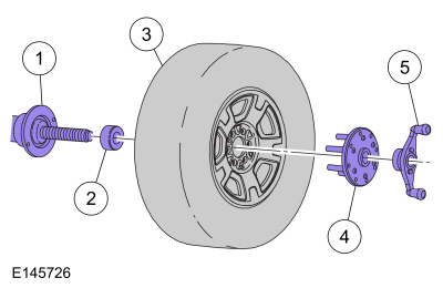
| Item | Description |
|---|---|
| 1 | Balancer |
| 2 | Cone |
| 3 | Wheel and Tire Assembly |
| 4 | Finger Plate |
| 5 | Balancer Wing Nut |
- Measure the Road Force®.
- Temporarily mark the high spot and the Road Force® value on the tire sidewall. If the wheel and tire assembly Road Force® exceeds 9 kg (20 lb), perform the matched mounting wheel and tire assembly optimization procedure.
- If the wheel and tire assembly Road Force® value is 9 kg (20 lb) or less, permanently mark the high spot and Road Force® value on the inside sidewall of the tire for future wheel and tire service reference. Balance the assembly and install the wheel and tire on the vehicle using the wheel-to-hub optimization procedure.
Radial Runout Measurement - Dial Indicator Method
- Make sure the tire pressure is set to the correct pressure specified on the VC label.
- Using tire chalk, mark the vehicle position on the inside sidewall of all 4 tires.
- Remove the wheel and tire assembly.
REFER TO: Wheels and Tires (204-04A Wheels and Tires, Removal and Installation). NOTICE: Make sure that the correct balancer adapters are used when mounting the assembly on the balancer, otherwise damage to the wheel may occur.
Mount the wheel and tire assembly on a suitable balancer using the correct balancer adapters, as shown in the illustration.
| Item | Description |
|---|---|
| 1 | Balancer |
| 2 | Cone |
| 3 | Wheel and Tire Assembly |
| 4 | Finger Plate |
| 5 | Balancer Wing Nut |
- Position a suitable dial indicator so that the indicator contacts the center rib of the tread.
- Rotate the wheel and tire assembly (or wheel) to locate the low point.
- Set the dial indicator to 0.
- Rotate the wheel and tire assembly one full revolution to confirm that the low point has been located and that the dial indicator returns to the 0 reading.
- Slowly and steadily rotate the wheel and tire assembly (or wheel) and measure the radial runout.
- Note the deflection (runout) from 0 on the dial indicator.
- If the wheel and tire assembly runout reading is greater than 1.14 mm (0.045 in), temporarily mark the high spot and runout reading on the tire sidewall and perform the match mounting procedure to optimize the wheel and tire assembly.
- If the wheel and tire assembly runout reading is 1.14 mm (0.045 in) or less, permanently mark the high point and runout reading on the inner tire sidewall for reference during future wheel and tire service. Balance the assembly and install the wheel and tire on the vehicle using the wheel-to-hub optimization procedure.

Test yourself
A quick Ford Escape quiz: every answer comes with an explanation and a link to the manual page.