Powertrain
Halfshaft - RH - Disassembly and Assembly
In this manual: Powertrain
9steps
~64min
4/5difficulty
2special tools
Done 0 of 9
Special Tool(s)
Material
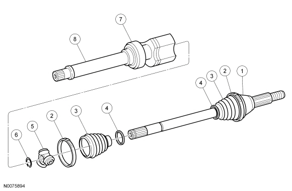
Disassembly NOTICE: The inner joint must not be bent at more than 18 degrees; the outer joint must not be bent at more than 45 degrees or damage to the component may occur.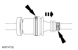
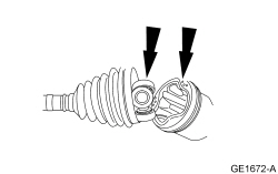
 Assembly NOTICE: The inner joint must not be bent at more than 18 degrees; the outer joint must not be bent at more than 45 degrees or damage to the component may occur.
 |
Installer, Constant Velocity Joint Boot Clamp 205-343 (T95P-3514-A) |
 |
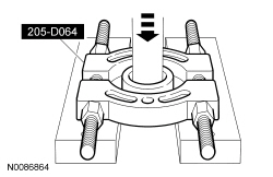
Puller, Bearing 205-D064 (D84L-1123-A) |
Material
| Item | Specification |
|---|---|
| Constant Velocity Joint Grease (High Temperature) XG-5 | WSS-M1C258-A1 |
| Item | Part Number | Description |
|---|---|---|
| 1 | 3B418 | Outboard fixed ball CV joint |
| 2 | 3B478 | Large CV boot clamps |
| 3 | 3A331 | Outboard CV boots |
| 4 | 3B478 | Small CV joint boot clamps |
| 5 | 3W007A | Tripod joint |
| 6 | 4B422 | Snap ring |
| 7 | 3B436 | Intermediate shaft support bearing |
| 8 | 3K183 | Intermediate shaft |
Disassembly NOTICE: The inner joint must not be bent at more than 18 degrees; the outer joint must not be bent at more than 45 degrees or damage to the component may occur.
- Remove the RH halfshaft assembly. For additional information, refer to Halfshaft — RH in this section.
- Clamp the intermediate shaft in a soft-jawed vise.
- Remove and discard the 2 inner boot clamps.
- Push back the boot along the shaft.
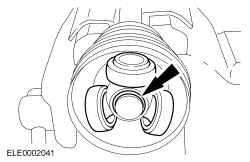
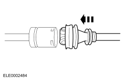
- Separate the tripod joint from the housing and remove all the grease.
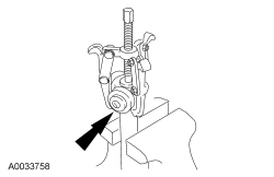
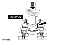
- Using the Bearing Puller and a suitable press, remove the intermediate shaft bearing.
- Remove and discard the snap ring.
- Using a suitable 3-jaw puller, remove the tripod.
- Remove and discard the inner CV joint boot and boot insert.
- Remove and discard the outboard CV joint boot.
- Remove and discard the 2 boot clamps.
- Remove and discard the boot.
- Remove the CV joint grease.
Assembly NOTICE: The inner joint must not be bent at more than 18 degrees; the outer joint must not be bent at more than 45 degrees or damage to the component may occur.
- Install the outboard boot and install half the grease in the sachet in the kit into the outer joint and the remainder in the CV joint boot.
- NOTICE: Use care not to damage the boot or component damage may occur.
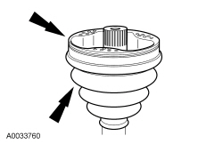
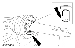
Position the boot on the outer CV joint.
- Slide a small flat-blade screwdriver under the boot seat to allow the air to escape.
- Locate the boot in position and remove the screwdriver.
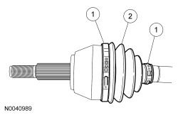
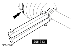
- Using the Constant Velocity Joint Boot Clamp Installer, install the 2 new clamps in boot ring grooves.
- NOTICE: Do not damage the tripod joint roller bearings or component damage may occur.
Install the tripod.
- Using a suitable driver, push the tripod onto the front drive halfshaft as far as it will go.
- Install the new snap ring.
- NOTE: Rotate the Bearing Puller so the flat side is facing upward. Make sure the inner bearing race is supported while pressing the bearing on.
Using the Bearing Puller and a suitable press, install the intermediate shaft bearing.
- Install half of the sachet of grease into the tripod housing. Inject the other half of the grease into the boot.
- Install the tripod joint into the tripod housing.
- Using the Constant Velocity Joint Boot Clamp Installer, install the 2 new inner CV boot clamps.
- Install the RH halfshaft assembly. For additional information, refer to Halfshaft — RH in this section.
Test yourself
A quick Ford Focus quiz: every answer comes with an explanation and a link to the manual page.
Was this page helpful?