Smart Junction Box (SJB)
 |
Vehicle Communication Module (VCM) and Integrated Diagnostic System (IDS) software with appropriate hardware, or equivalent scan tool |
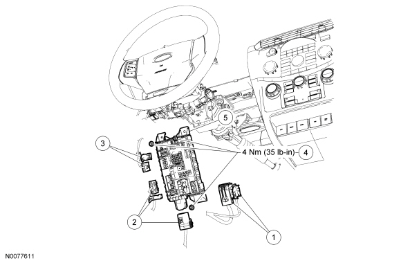
| Item | Part Number | Description |
|---|---|---|
| 1 | — | Electrical connectors (part of 14A005) |
| 2 | — | Electrical connectors (part of 14290) |
| 3 | — | Electrical connectors (part of 14401) |
| 4 | W701152-S | Smart Junction Box (SJB) nuts (3 required) |
| 5 | 15604 | SJB |
Removal NOTICE: Electronic modules are sensitive to static electrical charges. If exposed to these charges, damage to the module may result. NOTE:
Prior to the replacement of the module, it is necessary to upload the module configuration information to a scan tool. This information must be downloaded into the new Smart Junction Box (SJB) after installation. For additional information, refer to Section 418-01. In the event that As-Built data is required (SJB does not communicate), all Remote Keyless Entry (RKE) devices must be programmed to the new SJB . A minimum of 2 devices are necessary to complete the configuration and turn off the flashing interior lights.
NOTE:The Tire Pressure Monitoring System (TPMS) functionality is integral to the SJB .
NOTE:A new SJB is delivered in a "manufacturing mode" with 8 pre-set DTCs. A successful configuration of the SJB , then a successful TPMS sensor training, and a successful self-test including the clearing of all DTCs is required in order to clear the 8 manufacturing mode DTCs. The 8 manufacturing mode DTCs are:
- B106D (Tire Pressure Monitor System [TPMS ] Initiators Not Configured) This DTC is present when the SJB is not configured, even on applications that are not equipped with initiators.
- B2477 (Module Configuration Failure)
- B2868 (Left Front Tire Pressure Sensor Fault)
- B2869 (Right Front Tire Pressure Sensor Fault)
- B2870 (Right Rear Tire Pressure Sensor Fault)
- B2871 (Left Rear Tire Pressure Sensor Fault)
- B2A21 (One or More Configuration Files Missing or Corrupt)
- C2780 (ECU in Manufacturer Sub-State)
- NOTE: This step is only necessary if the SJB is being replaced.
Upload the module configuration information from the SJB into the scan tool. For additional information, refer to Section 418-01.
- Disconnect the electrical connectors.
- Remove the 3 nuts and the SJB .
- Position the SJB and install the 3 nuts.
- Tighten to 4 N·m.
- NOTE: If the SJB is not being replaced, this is the last step that is necessary.
Connect the 7 electrical connectors.
- NOTE: DTC B2276 may be set, indicating there are less than 2 transmitters programmed to the SJB . For additional information, refer to Section 501-14.
Download the SJB configuration information from the scan tool to the SJB . For additional information, refer to Section 418-01.
- Train the tire pressure sensors. For additional information, refer to Section 204-04.
- NOTE: DTC C2780 does not clear if any other DTCs are present in the SJB .
Carry out the SJB self-test (must include an on-demand self-test) and then repeat the self-test to confirm all DTCs (including DTC C2780) have been cleared.
- Rotate the instrument panel dimmer switch from the full dim position to the dome ON position. This makes sure that all displays are visible under all lighting conditions.
Test yourself
A quick Ford Focus quiz: every answer comes with an explanation and a link to the manual page.