Engine. Diagnosis and Testing
Inspection and Verification - Engine Performance
- Verify the customer concern.
- Visually check for obvious signs of mechanical or electrical damage.
- If an obvious cause for an observed or reported concern is found, correct the cause (if possible) before proceeding to the next step.
- If the cause is not visually apparent, connect the diagnostic tool to the DLC.
- If the diagnostic tool does not communicate with the VCM:
- Check the connection of the VCM to the vehicle.
- Check the connection of the diagnostic tool to the VCM.
- Check for no power on the scan tool to diagnose no power on the scan tool.
Refer to: Communication Network (Module 418-00 Communication Network, Diagnosis and Testing).
- If the diagnostic tool does not communicate with the vehicle:
- Make sure the ignition switch is in the ON position.
- Check the operation of the scan tool on a known good vehicle.
- To diagnose no response from the PCM,
Refer to: Communication Network (Module 418-00 Communication Network, Diagnosis and Testing).
- Perform the network test.
- If the scan tool reports no communication with one or more modules,
Refer to: Communication Network (Module 418-00 Communication Network, Diagnosis and Testing).
- If the network test passes, retrieve and record the continuous memory DTCs.
- If the scan tool reports no communication with one or more modules,
- Clear the continuous DTCs and perform a self-test diagnostic of the BCM (Battery Control Module) - HVTB (High Voltage Traction Battery) and PCM.
- If the DTCs retrieved relate to the concern, go to the BCM (Battery Control Module) - HVTB (High Voltage Traction Battery) DTC Chart. For all other DTCs, refer to the appropriate section 303-14.
- If no DTCs related to the concern are retrieved, GO to the Symptom Chart - Engine Performance.
Inspection and Verification - NVH
- NVH symptoms must be identified using the diagnostic tools and methods available. For a list of these methods, tools, an explanation of their use and a glossary of common terms,
Refer to: Noise, Vibration and Harshness (NVH) (100-04 Noise, Vibration and Harshness, Diagnosis and Testing).
As it is possible that any one of several systems may be the cause of the symptom, it may be necessary to use an elimination-type diagnostic approach to accurately identify the responsible system. - Verify the customer concern by starting the engine to duplicate the condition.
- Check the engine oil level and inspect the oil for contamination. Low engine oil level or contaminated oil are common causes of engine noise. If the oil is contaminated, the source of the contamination must be identified and corrected as necessary.
- Visually inspect for obvious signs of mechanical damage.
- If the inspection reveals obvious faults that can be easily identified, repair as necessary.
- If the cause is not visually apparent, connect the diagnostic tool to the DLC.
- If the diagnostic tool does not communicate with the VCM:
- Check the connection of the VCM to the vehicle.
- Check the connection of the diagnostic tool to the VCM.
- Check for no power on the scan tool to diagnose no power on the scan tool.
Refer to: Communication Network (Module 418-00 Communication Network, Diagnosis and Testing).
- If the diagnostic tool does not communicate with the vehicle:
- Make sure the ignition switch is in the ON position.
- Check the operation of the scan tool on a known good vehicle.
- To diagnose no response from the PCM,
Refer to: Communication Network (Module 418-00 Communication Network, Diagnosis and Testing).
- Perform the network test.
- If the scan tool reports no communication with one or more modules,
Refer to: Communication Network (Module 418-00 Communication Network, Diagnosis and Testing).
- If the network test passes, retrieve and record the continuous memory DTCs.
- If the scan tool reports no communication with one or more modules,
- Clear the continuous DTCs and perform a self-test diagnostic for the BCM-HVTB and PCM.
- If the DTCs retrieved relate to the concern, go to the BCM (Battery Control Module) - HVTB (High Voltage Traction Battery) DTC Chart. For all other DTCs, refer to the appropriate section 303-14.
- If no DTCs related to the concern are retrieved, continue with Inspection and Verification if the noise concern is engine related. For vibration and noise concerns such as the transmission mount, air intake system and starter, GO to the Symptom Chart - NVH.
In some cases, the noise may be a normal characteristic of this type of engine. In other cases, the noise may require further investigation. Comparing the noise to a vehicle of similar year/model equipped with the same engine will help determine whether the noise is normal or abnormal.
Once the customer concern has been identified as an abnormal engine noise, it is critical to determine the specific location of the noise. Use EngineEAR/ChassisEAR or a stethoscope (the noise will always be louder closer to the noise source) to localize the source of the noise to one of the following areas.
- Fuel injector(s)
- Upper end of the engine
- Lower end of the engine
- Front of the engine
- Rear of the engine
Fuel injector noise
A common source of an engine ticking noise may be the high-pressure fuel pump or fuel injectors on the GTDI (Gasoline Turbocharged Direct Injection) engine. This is normal engine noise that can be checked by listening to another vehicle. If the injector noise is excessive or irregular, use EngineEAR/ChassisEAR or a stethoscope to isolate the noise from a specific fuel injector.
Engine Noise - Upper Engine
A common source of upper engine noise (ticking, tapping or rattling), including the camshaft(s) and valvetrain, may be present. Upper end engine noise can be checked using EngineEAR/ChassisEAR or a stethoscope on the valve cover bolts. If the noise is loudest at the valve cover bolts, the noise is at the upper end. EngineEAR/ChassisEAR or a stethoscope can be used to further isolate the noise to a specific cylinder bank and cylinder. Removal of the valve cover(s) will be required to accurately determine the noise source.
Engine Noise - Low Engine
A common source of lower engine noise (ticking or knocking) includes the crankshaft, connecting rod(s) and bearings. Lower end noises can be identified at the oil pan or lower cylinder block. If the noise is loudest in these areas, the noise is lower end. If the engine noise is isolated to the lower end, some engine disassembly may be necessary to inspect for damage or wear.
Engine Noise - Front of Engine
A common source of front engine noise (squealing, chirping, screeching or humming) is the FEAD components. To isolate FEAD noise, perform the engine accessory check. Refer to: Noise, Vibration and Harshness (NVH) (100-04 Noise, Vibration and Harshness, Diagnosis and Testing).
Some other noises at the front of the engine (ticking, tapping or knocking) may be inside the engine. Use EngineEAR/ChassisEAR or a stethoscope on the front engine cover to determine if the noise is internal to the engine. Front engine cover removal may be necessary to inspect the internal engine components.
Engine Noise - Rear of Engine
A common source of noise at the rear of the engine (knocking) is the flywheel/flexplate. Inspection of the flywheel/flexplate will be necessary.
Some engines have valvetrain drive components at the rear of the engine and may be a source of noise (ticking, tapping or rattling). Use EngineEAR/ChassisEAR or a stethoscope at the rear of the engine if the noise is suspected to be internal to the engine. Some disassembly may be necessary to inspect the engine for damage or wear.
GTDI (Gasoline Turbocharged Direct Injection) Turbocharger Noise
A common source of noise is the turbocharger. A slight whine or airflow noise is an acceptable condition.
Follow the steps below to determine the source of the engine noise. Compare the engine noise characteristics with those listed in the NVH chart.
- Using a stethoscope, attempt to locate the source of the engine noise. Note the location of any suspicious noises heard with the stethoscope.
Click here to view engine noise diagnosis using a stethoscope.

- If the noise is unclear using the stethoscope, attach the Chassis EAR at several locations on the engine. Attach the Chassis EAR to the suspected noise areas and to areas not suspected as the noise source for comparison. The Chassis EAR allows up to 6 clamps to be used to locate the source of the noise. Instead of or in addition to using the Chassis EAR, the EngineEAR can also be used. Wave or hold the EngineEAR over suspected areas of the engine to help determine the suspected noise.
Click here to view engine noise diagnosis using the ChassisEAR.

Click here to view engine noise diagnosis using the EngineEAR.

- If the noise is still unclear using the stethoscope, ChassisEAR or EngineEAR, connect the scan tool. Use the VCMM oscilloscope function to view and graph the noise. Attach VCMM accelerometers at the loudest suspected locations identified earlier with the stethoscope, Chassis Ears or EngineEAR. Using the scan tool and VCMM accelerometers, graph the noise on the oscilloscope and determine whether the noise is upper or lower engine noise. For upper engine noise, place the accelerometers on both ends of the valve cover. For lower engine noise, place the accelerometers on either end or on the side-to-side of the engine block.
Click here to view engine noise diagnosis using the VCMM and accelerometers.

- If the noise remains unclear, or to verify the suspected noise from the stethoscope, ChassisEAR, EngineEAR or accelerometers graph, use a 3.5 mm male-to-female RCA adapter to connect the ChassisEAR or EngineEAR to the VCMM. Graph all or some of the noises, such as the accelerometers.
Click here to view engine noise diagnosis using the VCMM and ChassisEAR.

Click here to view engine noise diagnosis using the VCMM and EngineEAR.

- If the location of the suspected noise still cannot be determined, use the VCMM oscilloscope function to graph any combination of accelerometer(s), ChassisEAR and/or EngineEAR to compare or identify the suspected noise. All 4 ports on the VCMM can be used to graph the noise.
Click here to view engine noise diagnosis using the VCMM, ChassisEAR and accelerometer(s).

Click here to view engine noise diagnosis using the VCMM, EngineEAR and accelerometer(s).

- After locating the noise, note the noise characteristics, including the type of noise, frequency and the conditions under which the noise occurs, and GO to the Symptom Chart - NVH.
Symptom Chart - Engine Performance
Symptom Chart - Engine Performance| Symptom | Possible Sources | Action |
|---|---|---|
|
|
|
|
|
|
|
|
|
|
|
|
|
|
|
|
|
|
|
|
|
|
|
|
|
|
|
|
|
|
|
|
|
|
|
|
|
|
|
|
|
|
|
|
|
|
|
|
|
|
|
|
|
|
|
|
|
|
|
|
|
|
|
|
|
|
|
|
|
|
|
|
|
|
|
|
|
|
|
|
|
|
|
|
|
|
|
|
|
|
|
|
|
|
|
|
|
|
|
|
|
|
|
|
|
|
|
|
|
|
|
|
|
|
|
|
|
|
|
|
|
|
|
|
|
|
|
|
|
|
|
|
|
|
|
|
|
|
|
|
|
|
|
|
|
|
|
|
|
|
|
|
|
|
|
|
|
|
|
|
|
|
|
|
|
|
|
|
|
|
|
|
|
|
|
|
|
|
|
|
|
|
|
|
|
|
|
|
|
|
|
|
|
|
|
|
|
|
Symptom Chart - NVH
Symptom Chart - NVH| Symptom | Possible Sources | Action |
|---|---|---|
|
|
|
|
|
|
|
|
|
|
|
|
|
|
|
|
|
|
|
|
|
|
|
|
|
|
|
|
|
|
|
|
|
|
|
|
|
|
|
|
|
|
|
|
|
|
|
|
|
|
|
|
|
|
|
|
|
|
|
|
|
|
|
|
|
|
|
|
|
|
|
|
|
|
|
|
|
|
|
|
|
|
|
|
|
|
|
|
|
|
|
|
|
|
|
|
|
|
|
|
|
|
|
|
|
|
|
|
|
|
|
|
|
|
|
|
|
|
|
|
|
|
|
|
|
|
|
|
|
|
|
|
|
|
|
|
|
|
|
|
|
|
|
|
|
|
|
|
|
|
|
|
|
|
|
|
|
|
|
|
|
|
|
|
|
|
|
|
|
|
|
|
|
|
|
|
|
|
|
|
|
|
Component Tests
The following component tests are used to diagnose engine problems.
Engine Oil Leaks
Before performing this procedure, clean the cylinder block, cylinder heads, valve covers, oil pan and flywheel/flexplate with a suitable solvent to remove all traces of oil.
Engine Oil Leaks - Fluorescent Oil Additive Method
Use the UV Long-Wave W/12-ft Cord & Alligator Clips (164-R3748) or the Leak Tracker UV LED Flashlight (164-TP8695) to perform the following oil leak diagnostic procedure.
- Add 29.6 ml (1 oz) of Dye-Lite® Oil-Based Liquid Dye (164-TP33200601) to a minimum of 0.5 L and a maximum of 0.9 L of engine oil. Thoroughly pre-mix the oil-based liquid dye, otherwise it will not reach the sump, oil galleries and sealing surfaces during this specific 15-minute test. The additive must be added through the oil filler. Check the level using the oil level indicator to determine how much oil must be pre-mixed. If it is in the middle of the shaded area or below the full mark, use 0.9 L. If it is at the full mark, use 0.5 L.
- Run the engine for 15 minutes. Stop the engine and inspect all seal and gasket areas for leaks using the UV leak detector kit. A white fluorescent area identifies a leak. For extremely small leaks, it may take several hours for the leak to appear.
- At the end of the inspection, make sure the oil level is within the upper and lower marks on the oil level indicator. If necessary, remove oil if the level is registered above the full mark.
Leak Points - Under Hood
Inspect the following locations for oil leaks:
- Valve cover gaskets
- High-pressure fuel pump seal
- Cylinder head gaskets
- Oil Cooler, if equipped
- Oil Filter Adapter
- Front Engine Cover
- Oil filter adapter and filter housing
- Oil level indicator tube connection
- Oil pressure switch or EOP sensor
- Vacuum pump to cylinder head
- CAC to intake manifold
- Turbocharger oil lines
Leak Points - Under Engine, Vehicle on Lift
Inspect the following locations for oil leaks:
- Oil pan gaskets
- Oil pan seal
- Front engine cover gasket
- Crankshaft Front Seal
- Rear Crankshaft Seal
- Oil filter adapter and filter housing
- Oil Cooler, if equipped
- Oil pressure switch or EOP sensor
- CAC to intake manifold
- Turbocharger oil lines
Leak Points - Transaxle and Flywheel/Flexplate Removed
Inspect the following locations for oil leaks:
- Rear Crankshaft Seal
- Rear main bearing cap parting line
- Flexplate bolt holes (with flexplate installed)
- Oil gallery plugs
Compression Test - Hybrid
To perform a compression test, the engine must be cranked for at least 5 compression strokes with the throttle wide open for each cylinder. The Engine Start Diagnostic Mode must be used to crank the engine, and the brake/accelerator pedals must be used to set the throttle position during the compression test. The Engine Start Diagnostic Mode is a PCM strategy that differs from the normal operating strategy. It allows the engine to start similarly to a conventional vehicle with fuel disabled. In this mode, the PCM commands the TCM to rotate the generator, which cranks the engine at a speed between 900 and 1200 rpm. The engine will crank as long as the traction battery state of charge remains above 35%.
- Make sure the engine oil is of the correct viscosity and at the correct level. Drive the vehicle until the engine is at normal operating temperature.
- Using the scan tool, access the BCM (Battery Control Module) - HVTB (High Voltage Traction Battery) and monitor the traction battery state of charge PID. If the monitored PID shows a state of charge below 45%, start the engine and let it idle with the full air conditioner ON. When the traction battery state of charge exceeds 45%, the Engine Start Diagnostic Mode can be activated.
- Turn the ignition switch to the OFF position, then remove all spark plugs.
- Install a compression gauge, such as a quick-release compression gauge, into cylinder No. 1.
- Activate the engine start diagnostic mode as follows:
- Apply the parking brake.
- Place the transmission selector lever in the PARK position.
- Make sure the key is in the OFF position.
- With the engine off, turn the ignition key to the ON position.
- Within 5 seconds of turning the key to ON, fully depress the accelerator pedal and hold it for 10 seconds.
- Within 5 seconds, release the accelerator pedal, move the gear selector to the NEUTRAL position, and fully depress the accelerator pedal.
- Hold the fully depressed accelerator pedal for 10 seconds.
- Release the accelerator pedal and move the gear selector to the PARK position.
- If the sequence is performed correctly, the IC (Instrument Cluster) hazard indicator (red triangle) flashes once per second when the transmission selector lever is in PARK. The PCM exits the engine start diagnostic mode when the traction battery state of charge drops below 35%, when the transmission selector lever is moved to any position other than PARK, or when the ignition switch is turned to OFF or ACC.
- Crank the engine as follows:
- Press and hold the brake pedal.
- Fully depress and hold the accelerator pedal.
- Turn the key to the START position and crank the engine for a minimum of 5 compression strokes, and record the maximum value. Return the key to the ON position.
- Release the accelerator pedal.
- Release the brake pedal.
- Repeat the test on each cylinder, cranking the engine for approximately the same number of compression strokes.
- Turn the key to the OFF position to deactivate the engine start diagnostic mode.
- Clear all DTCs.
Compression Test - All vehicles except hybrid
- Make sure the engine oil is of the correct viscosity and at the correct level, and that the battery is fully charged. Drive the vehicle until the engine reaches normal operating temperature. Turn the ignition switch to the OFF position, then remove all spark plugs.
- Set the throttle valves to the fully open position.
- Install the compression gauge in cylinder No. 1.
- Install the auxiliary starter switch in the starting circuit. With the ignition switch in the OFF position and using the auxiliary starter switch, crank the engine for a minimum of 5 compression strokes and record the maximum reading. Note the approximate number of compression strokes required to obtain the highest reading.
- Repeat the test on each cylinder, cranking the engine for approximately the same number of compression strokes.
Compression Test - Test Results
The specified compression pressures are considered within specification if the cylinder with the lowest reading is at least 75% of the highest reading. Refer to the Compression Pressure Limits table.
Compression Pressure Limit Values Table

If one or more cylinders read low, inject approximately one tablespoon of Ford-approved engine oil into the cylinders with low readings through the spark plug holes. Repeat the compression pressure test on those cylinders.
Compression Test - Compression Test Interpretation
- If compression improves significantly, the piston rings are worn or damaged.
- If compression does not improve, the valves are sticking or not seating correctly.
- If 2 adjacent cylinders show low compression and compression does not increase when oil is added to each piston, the cylinder head gasket between the cylinders may be leaking. Engine oil or coolant in the cylinders may result from this condition. Use the Compression Pressure Limits table. If the lowest cylinder value is within 75% of the highest value, the test is acceptable.
Cylinder Leakage Test
When a cylinder reads low, use a cylinder leakage tester to help determine the exact cause.
Insert the leakage tester into the spark plug hole, position the piston at TDC on the compression stroke, and supply compressed air.
Once the combustion chamber is pressurized, read the percent leakage on the leakage tester gauge. Leakage exceeding 20% is excessive.
While the air pressure in the cylinder is maintained, listen for hissing escaping air. A leak at the intake valve will be heard at the TB (throttle body). A leak at the exhaust valve will be heard at the exhaust pipe. A leak past the piston rings will be heard at the PCV connection. If air passes through a damaged head gasket into an adjacent cylinder, the noise will be heard at the spark plug hole of the cylinder receiving the air. Cracks in the cylinder block or a coolant system gasket leak may be detected by a stream of bubbles in the radiator.
Excessive Engine Oil Consumption
Nearly all engines consume some oil, which is necessary for normal lubrication of the cylinder walls, pistons and rings. To determine if the oil consumption is excessive, it may be necessary to check oil consumption by recording the quantity of oil added over a set number of miles.
Customer driving habits greatly affect oil consumption. Accumulated mileage while towing or carrying heavy loads generates additional heat. Frequent short trips, stop-and-go driving, or prolonged idling prevent the engine from reaching normal operating temperature. This prevents component clearances from reaching specified operating ranges.
The following diagnostic procedure can be used to determine internal oil consumption. Make sure the concern is internal oil consumption and not external leaks, which also consume oil. Verify there are no external leaks before performing the test. After verification, the rate of internal oil consumption can be checked.
A new engine may require additional oil during the early stages of operation. The internal clearance between the piston and bore and the sealing characteristics improve as the engine breaks in. Engines are built to tight tolerances and do not require break-in oils or additives. Use the oil specified in the Owner's Literature. Ambient temperature may determine the oil viscosity specification. Make sure the oil is correct for the vehicle in the geographic region where it is operated.
Basic Preliminary Checks
- For customer complaints of oil consumption, interview the customer to determine oil consumption characteristics. If possible, determine the brand and grade of oil currently in the crankcase. Check the oil filter label or oil change station records to determine whether the Ford-recommended maintenance schedule was followed. Make sure the oil was changed at the specified mileage intervals. If vehicle mileage exceeds the first recommended change interval, the OEM (original equipment manufacturer) production filter may have been changed.
- Ask how the most recent mileage was accumulated. Determine whether the vehicle was operated under the following conditions:
- Prolonged engine idling or idling on the shoulder
- Stop-and-go or taxi operation
- Towing a trailer or heavily loaded vehicle
- Frequent short trips (engine not warmed up to normal operating temperature)
- Excessive throttling or high engine speed driving
- Check for external leaks. If necessary, review the diagnostic procedure in the Engine Oil Leaks section under Diagnosis and Testing in this section.
- Inspect the crankcase ventilation system for:
- disconnected hoses at the valve cover or TB.
- loose or missing valve cover oil filler cap.
- missing or incorrectly installed engine oil dipstick.
- incorrect or dirty PCV valve.
- PCV valve grommet not installed in the valve cover (if equipped).
- Inspect for signs of sludge. Sludge affects PCV system performance and may clog or restrict the cylinder head drain passages. It can also increase oil pressure by restricting oil passages and reducing the ability of the piston oil control rings to drain. Sludge may form either from excessive water entering the crankcase or from operating at very high crankcase temperatures.
- Inspect the ACL for dirt, sludge, or damage. A hole in the filter element will allow unfiltered air to enter the air induction system. This can cause premature internal wear (dust engine), allowing oil to bypass the rings, pistons, valves, and guides.
- If the engine is hot or has recently been shut off, wait at least 15 minutes to allow the oil to drain back. Ask the customer if this requirement was observed. Adding oil without this waiting period may cause an overfill condition, resulting in excessive oil consumption and foaming, which can damage the engine.
- Make sure the oil level indicator (dipstick) is correctly and fully inserted into the indicator tube. Remove the oil level indicator and record the oil level.
Detailed Preliminary Checks
- Check the thermostat opening temperature to make sure that the cooling system operates at the specified temperature. If it is low, the internal engine components will not operate within the specified internal operating clearances.
- Make sure the spark plugs are not saturated with oil. Oil leakage into one or more cylinders will appear as an oil-soaked condition on the plug. If a spark plug is saturated, a compression test may be needed upon completion of the oil consumption test.
Oil Consumption Test
- Drain the engine oil and remove the oil filter. Install a new oil filter specified by the manufacturer. Make sure the vehicle is on a level surface. Fill the oil pan to one quart (liter) below the specified fill level, using the oil specified by the manufacturer.
- Run the engine for 3 minutes (if hot) or 10 minutes (if cold). Allow a drain period of at least 15 minutes, then record the oil level shown on the dipstick. Make a mark on the back of the dipstick indicating the oil level position.
- Add the last quart (liter) to complete the normal oil fill. Restart the engine and let it idle for 2 minutes. Shut down the engine.
- After a 15-minute drain-back period, record the oil level location again. Mark the oil level indicator with the new oil level location. (Note: both marks should be very close to the MIN-MAX, upper and lower limits, or upper and lower holes on the oil level indicator. These marks will accurately measure engine oil consumption, with a difference of one quart between the new marks.) Demonstrate to the customer that the factory calibration marks on the oil level indicator, where the oil should drop after an oil change with the specified fill amount. Explain, however, that this may vary slightly between the MIN-MAX or upper and lower holes of the oil level indicator.
- Record the vehicle mileage.
- Inform the customer that the oil level indicator readings must be checked every 320 km (200 miles) or weekly, using the revised estimates as shown. Remind the customer that the engine requires a minimum 15-minute drain-back for accurate readings, and that the oil level indicator must be fully seated in the tube before taking readings.
- When subsequent indicator readings show that one full quart has been consumed, record the vehicle mileage. The mileage must be at least 4800 km (3000 miles). The driving cycle of the vehicle must be taken into account during this calculation. The customer may need to bring the vehicle in for periodic oil level indicator readings to closely monitor oil consumption.
Follow-Up Checks, Evaluation and Corrective Actions
- If the test results indicate excessive oil consumption, perform a cylinder compression test. The cylinder compression test should be performed with a fully charged battery and all spark plugs removed. Refer to the Compression Test Specifications table in this section for range limits.
- Compression should be equal in all cylinders. Refer to the Compression Test section in this section. If compression is within the specifications given in this section, excessive oil consumption may be caused by worn valve guides, valves, or valve stem seals.
- A cylinder leakage test may be performed using a cylinder leak detector. This can help identify valves, piston rings, worn valve guides/valve stems, faulty valve stem seals, or other adjacent areas as the source of oil consumption.
- If internal engine damage is isolated as the root cause, determine whether the repair will exceed cost limits, and proceed with a repair strategy as required.
- After completing the corrective actions on the engine and verifying that all pre-check items have been cleared in the original diagnosis, repeat the oil consumption test as described above and check the consumption results.
Intake Manifold Vacuum Test
Bring the engine to normal operating temperature. Connect a vacuum/pressure gauge to the intake manifold. Run the engine at the specified idle speed.
The vacuum gauge should read between 51 and 74 kPa (15-22 in Hg) depending on engine condition and the altitude at which the test is performed. Subtract 4.0193 kPa (1 in Hg) from the specified reading for every 304.8 m (1000 ft) above sea level.
The reading should be steady. If necessary, adjust the gauge damper control (where equipped) if the needle fluctuates rapidly. Adjust the damper until the needle moves easily without excessive flutter.
Intake Manifold Vacuum Test - Vacuum Gauge Reading Interpretation
A careful study of the vacuum gauge readings at engine idle will help identify problem areas. Always perform other applicable tests before making a final diagnosis. Vacuum gauge readings, while useful, must be interpreted with caution.
Most vacuum gauges have a normal range marked on the gauge face. Possible gauge readings are listed below. Some are normal; others must be investigated further.
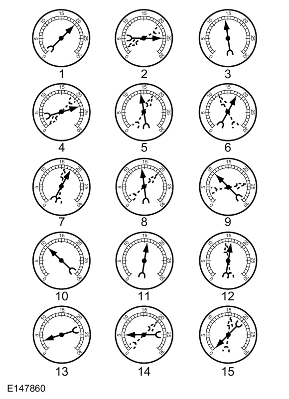
- NORMAL READING: The needle is within 51-74 kPa (15-22 in Hg) and holds steady.
- NORMAL READING DURING QUICK ACCELERATION AND DECELERATION: When the engine is quickly accelerated (dotted needle), the needle will drop to a low value (not to zero). When the throttle is suddenly released, the needle will rise again above the normal figure.
- NORMAL FOR HIGH-LIFT, LONG-DURATION CAMSHAFT: The needle will register at 51 kPa (15 in Hg) but will be relatively steady. Some fluctuation is normal.
- WORN RINGS OR DILUTED OIL: When the engine accelerates (dotted needle), the needle drops to 0 kPa (0 in Hg). On deceleration, the needle rises slightly above 74 kPa (22 in Hg).
- STICKING VALVES: When the needle (dotted) remains steady at normal vacuum but occasionally flicks (sharp, quick movement) down and back about 13 kPa (4 in Hg), one or more valves may be sticking.
- BURNED OR WARPED VALVES: A regular, evenly spaced downward movement of the needle across the scale indicates one or more burned or warped valves. Insufficient valve clearance may also cause this reaction.
- POOR VALVE SEATING: A small but regular downward flick of the needle may indicate that one or more valves are not seating properly.
- WORN VALVE GUIDES: When the needle fluctuates approximately 13 kPa (4 in-Hg) at idle, the valve guides may be worn. As engine speed increases, the needle stabilizes if the guides are serviceable.
- WEAK VALVE SPRINGS: When needle fluctuation increases with engine speed, the valve springs are weak. Refer to specifications. Idle reading may be relatively steady.
- LATE VALVE TIMING: A steady but low reading may be caused by late valve timing.
- RETARDED IGNITION TIMING: Retarded ignition timing will produce steady but slightly low readings.
- SPARK PLUG GAP TOO NARROW: When the spark plug gap is too narrow, a regular small needle pulsation may occur.
- INTAKE LEAK: Low, steady readings may be caused by a leak in the intake manifold or TB gasket.
- HEAD GASKET LEAK: A regular drop of significant magnitude may be caused by a blown cylinder head gasket or cylinder head-to-block surface distortion.
- RESTRICTED EXHAUST SYSTEM: When the engine is started and running at idle, readings may be normal, but when engine speed is increased, back pressure caused by a clogged muffler, kinked exhaust pipe or other problems will cause the needle to slowly drop to 0 kPa (0 in-Hg). The needle may then slowly rise. Excessive exhaust restriction will cause the needle to drop to the lowest point, even at idle.
When a vacuum leak is detected, locate and correct the cause. Excess air entering the system will disrupt the air-fuel mixture and cause problems such as rough idle, poor acceleration or burned valves. If the leak is in an accessory unit, such as the brake booster, the unit will not operate correctly. Always correct vacuum leaks.
Engine Oil Pressure Test
- Disconnect and remove the oil pressure sensor (refer to Engine 303-01) or the EOP sensor (refer to Section 303-14).
- Connect a commercially available oil pressure gauge to the oil pressure sensor port on the oil gallery.
- Run the engine until normal operating temperature is reached.
- Run the engine at the specified speed and record the gauge reading.
- Engine oil pressure must be within specification. Refer to the specifications table in the appropriate engine section 303-01.
- If the pressure is not within specification, check the following possible causes:
- Insufficient engine oil
- Oil leak
- Worn or damaged oil pump
- Oil pump screen cover and tube
- Excessive main bearing clearance
- Excessive connecting rod bearing clearance
- Timing Chain Tensioner Leak
- Remove the commercially available oil pressure gauge.
- Install and connect the oil pressure sensor (refer to Engine 303-01) or the EOP sensor (refer to Section 303-14).
Valvetrain Analysis - All Engines Except 2.7 L Ecoboost
The following component tests are used to diagnose valvetrain concerns.
Valvetrain Analysis - Engine Off, Valve Cover Removed
Inspect for damaged or excessively worn components and correct assembly. Make sure the correct parts are used with the engine static analysis as follows.
Valvetrain Analysis — Camshafts and Valve Lifters
- Check for broken or damaged components.
- Check that the camshaft cap bolts are not loose.
- Check for worn or damaged valve lifters.
Valvetrain Analysis — Valve Springs, Valve Lifters Removed
- Check for broken or damaged components.
Valvetrain Analysis — Valve Spring Retainer and Valve Spring Retainer Locks, Valve Lifters Removed
- Check that the valve spring retainer locks are correctly seated on the valve stem and in the valve spring retainer.
- Check correct seating on the valve stem.
Valvetrain Analysis — Valves and Cylinder Head, Valve Lifters Removed
- Check that the rear oil drain holes are not blocked.
- Check for worn or damaged valve tips.
- Check for missing or damaged valve stem seals or valve stem seal installed on the guide.
- Check for missing or worn valve spring seats.
Valvetrain Analysis - Camshaft Lobe Lift
Check the lift of each camshaft lobe in sequence and record the readings.
- Remove the spark plugs. Refer to Section 303-07.
- Install the dial indicator with the holder so that the rounded tip of the dial indicator plunger is on top of the camshaft lobe and in line with the valve lifter.

- Rotate the crankshaft using a breaker bar and socket attached to the crankshaft pulley bolt. Rotate the crankshaft until the camshaft lobe base circle is reached.
- Zero the dial indicator. Continue rotating the crankshaft until the camshaft lobe is in the fully raised position (maximum indicator reading).
- To verify the accuracy of the original dial indicator reading, continue rotating the crankshaft until the base circle is reached. The indicator reading must be zero. If zero is not obtained, repeat steps 2 through 5.
- If the lift on any lobe is below the specified limit, install a new camshaft and roller followers or valve lifters.
- Install the spark plugs. Refer to Section 303-07.
Valvetrain Analysis - 2.7 L Ecoboost
The following component tests are used to diagnose valvetrain concerns.
Valvetrain Analysis - Engine Off, Valve Cover Removed
Check for damaged or excessively worn components and correct assembly.
Valvetrain Analysis - Camshaft Lobe Lift
Check the lift of each camshaft lobe in sequence and record the readings.
- Remove the spark plugs.
Refer to: Spark Plugs (Engine Ignition System 303-07D - 2.7 L EcoBoost (238 kW/324 L hp), Removal and Installation). - Install the dial indicator with the holder so that the rounded tip of the dial indicator plunger is on top of the camshaft lobe and in line with the valve lifter.

- Rotate the crankshaft using a breaker bar and socket attached to the crankshaft pulley bolt. Rotate the crankshaft until the camshaft lobe base circle is reached.
- Zero the dial indicator. Continue rotating the crankshaft until the camshaft lobe is in the fully raised position (maximum indicator reading).
- To verify the accuracy of the original dial indicator reading, continue rotating the crankshaft until the base circle is reached. The indicator reading must be zero. If zero is not obtained, repeat steps 2 through 5.
- If the lift on any lobe is below the specified limit, install a new camshaft and roller followers or valve lifters.
- Install the spark plugs.
Refer to: Spark Plugs (Engine Ignition System 303-07D - 2.7 L EcoBoost (238 kW/324 L hp), Removal and Installation).
Test yourself
A quick Ford Fusion quiz: every answer comes with an explanation and a link to the manual page.