Heating, Ventilation, and Air Conditioning
Heater and A/C Control Unit (DATC) Repair Procedures
In this manual: Heating, Ventilation, and Air Conditioning
10steps
~60min
3/5difficulty
Done 0 of 10
Self-Diagnosis
- Self-Diagnosis Procedure.
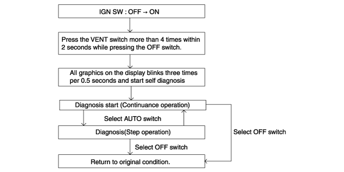
- Trouble Code Display
- Continuous Operation: DTC.

- Continuous Operation: DTC.

- STEP operation. A. Normal code or one trouble code is the same as continuous operation. B. Trouble code.
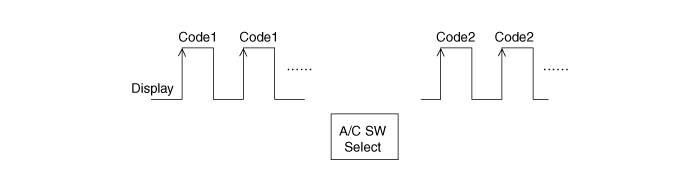
- Continuous Operation: DTC.
- If any diagnostic trouble codes are displayed during the inspection, check the causes of the malfunction by referring to the DTC troubleshooting.
Display Description of Malfunction 0 Normal 11 Incar sensor OPEN 12 Incar sensor SHORT 13 Ambient sensor OPEN 14 Ambient air sensor SHORT 17 Evaporator sensor OPEN 18 Evaporator sensor SHORT 19 Driver side temperature potentiometer OPEN or SHORT 20 Driver side potentiometer malfunction 21 Mode door potentiometer OPEN or SHORT 22 Mode door potentiometer malfunction 23 Auto defog sensor OPEN 24 Auto defog sensor SHORT 25 Intake door potentiometer OPEN or SHORT 26 Intake door potentiometer malfunction 32 Passenger side temperature potentiometer OPEN or SHORT 33 Passenger side temperature sensor malfunction 45 APT CAN signal error 47 RPM CAN signal error 48 Vehicle speed CAN signal error 49 Engine coolant temperature CAN signal error 50 Cluster ionizer malfunction 71 ECV error (OPEN) - Fail-safe
NO Item Fault Fail-safe 1 Incar sensor Open or short Monitor value 25 °C 2 Ambient sensor Open or short Monitor value 20 °C 3 Evaporator sensor Open or short Monitor value -2°C (28.4°F) 4 Mode door potentiometer Open or short Fix the vent position when selecting the vent mode.
Fix the defrost position by selecting any mode except the vent mode.5 Temperature door potentiometer (MTC) Open or short If the temperature setting is 1 ~ 7 steps, fix the position to maximum cooling.
If the temperature setting is 8 ~ 15 steps, fix the position to maximum heating.6 Temperature door potentiometer (DATC) Open or short If the set temperature is 17 °C ~ 24 °C, fix the position to maximum cooling.
If the set temperature is 25 °C ~ 32 °C, fix the position to maximum heating.7 Intake door potentiometer Open or short Fix the vent position when selecting the vent mode.
Fix the defrost position by selecting any mode except the vent mode.8 Engine Speed FFh or no reception A/C OFF (Control with value 650 rpm) 9 Vehicle Speed FFh or no reception A/C OFF 10 Engine Coolant Temperature FFh or no reception Monitor value - 2 °C 11 APS FFh or no reception Monitor value 5% 12 R-TQACNAPVC
(A/C compressor maximum torque limit)FFh or no reception A/C OFF (Control with value 0 N·m) 13 R-PAKNK
(APT sensor output value)FFh or no reception A/C OFF (Control with value 0 N·m) 14 RLY-AC
(A/C compressor relay activation)FFh or no reception FFh
Replacement
- Disconnect the negative (-) battery terminal.
- Remove the glove box upper cover assembly. (Refer to Body - "Glove Box Upper Cover Assembly")
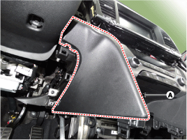
- Loosen the mounting screws and remove the center lower airbag cover [LH] (A).
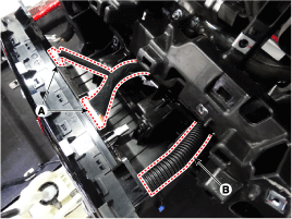
- Loosen the mounting screws, then remove the air conditioner and heater control assembly (A).

- Disconnect the connectors of the air conditioner and heater controller (A) and the hose (B).
- To install, reverse the removal procedure.

- Make sure the connector is properly connected.
- Replace all damaged clips.
Test yourself
A quick Hyundai Elantra AD quiz: every answer comes with an explanation and a link to the manual page.
Was this page helpful?