Body Electrical System
General Information
In this manual: Body Electrical System
74steps
~444min
4/5difficulty
Done 0 of 74
General Troubleshooting Information
Before Troubleshooting- Check the related fuses in the applicable fuse/relay box.
- Check the battery for damage, state of charge, cleanliness and secure connections. (Refer to Engine Electrical System - "Battery")

- Do not perform a quick charge of the battery if the battery ground cable has been disconnected, otherwise the generator diodes will be damaged.
- Do not try to start the engine with the battery ground cable loosely connected, otherwise the wiring will be seriously damaged.
- Check the generator belt tension (D).
- Make sure the connectors are clean and there are no loose wire terminals.
- Make sure multi-cavity connectors are filled with grease (except waterproof connectors).
- All connectors have push-type locks (A).
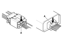
- Some connectors have a clip on the side used to secure them to the mounting bracket on the housing or other component. This clip has a pull-type lock.
- Some mounted connectors cannot be disconnected unless you first release the lock and remove the connector from the mounting bracket (A).
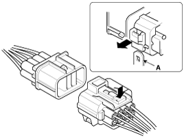
- Never try to disconnect connectors by pulling on their wires; instead, pull on the connector halves.
- Always reinstall plastic covers.
- Before connecting connectors, make sure the terminals (A) are in place and not bent.
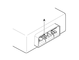
- Check that the lock (A) and rubber seals (B) are not loose.
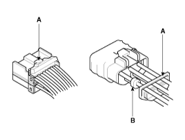
- The rear of some connectors is filled with grease. Add grease if necessary. If the grease (A) is contaminated, replace it.
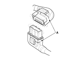
- Insert the connector fully and make sure it is securely locked.
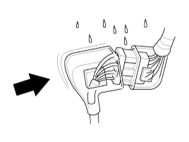
- Route the wires so that the open end of the cover faces downward.
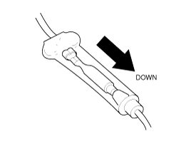
- Secure the wires and wire harnesses to the frame with the appropriate clamps at the designated locations.
- Carefully remove the clips; do not damage their locks (A).
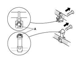
- Insert pliers (A) under the clip base and through the hole at an angle, then squeeze the spreader projections to release the clip.
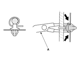
- After installing the seat belt clips, make sure the seat belt does not interfere with moving parts.
- Keep wire harnesses away from exhaust pipes and other hot parts, sharp edges of brackets and holes, and exposed screws and bolts.
- Correctly install the grommets into the grooves (A). Do not leave grommets deformed (B).
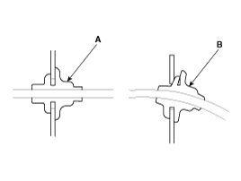
- Do not use wires or harnesses with damaged insulation. Replace them or repair them by wrapping the break with insulating tape.
- After installing parts, make sure wires are not pinched under them.
- When using electrical test equipment, follow the manufacturer's instructions and the instructions described in this manual.
- If possible, insert the removal tool from the wire side (except waterproof connectors).
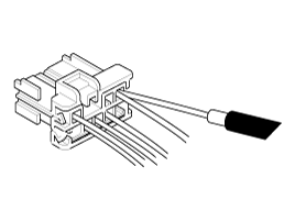
- Use a probe with a tapered tip. Refer to the wiring repair kit user's manual (publication number: TRK 015).
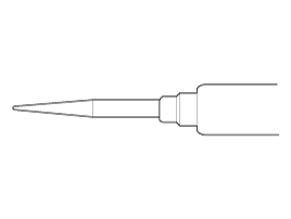
- Verify the Customer Complaint: Operate all components in the problem circuit to verify the customer complaint. Note the symptoms. Do not begin disassembly or testing until you have narrowed down the problem area.
- Analyze the Circuit: Find the schematic of the problem circuit. Determine how the circuit should operate by tracing the current path from the power source through the circuit components to ground. If several circuits fail at the same time, the fuse or ground is the likely cause. Based on the symptoms and your understanding of circuit operation, identify one or more possible causes of the problem.
- Isolate the Problem by Testing the Circuit: Perform circuit tests to check the diagnosis made in step 2. Keep in mind that a logical and simple procedure is the key to efficient troubleshooting. First check the most likely cause of failure. Try to perform tests in easily accessible locations.
- Repair the Problem: Once the specific problem is identified, make the repair. Be sure to use proper tools and safe procedures.
- Verify the Circuit Operates: Operate all components in the repaired circuit in all modes to make sure you have fixed the entire problem. If a fuse was blown, be sure to check all circuits on that fuse. Make sure no new problems appear and the original problem does not recur.
- Install the antenna on the roof or rear bumper.
- Antenna cables must be routed more than 200 mm (7.9 in) away from the computer or harness, because antenna cables transmit radio signals.
- Reduce the standing wave ratio by using suitable antennas and cables.
- Do not install a remote control with high output power.
- Check the engine condition by generating radio signals at idle.
Standing Wave Ratio: The input impedance Zi may change depending on the length of the cables, and the signal range of the remote control under the condition that the resistance is connected to other cables, antennas, and replacement parts. The ratio of maximum to minimum voltage is called the standing wave ratio. This means the ratio of antenna impedance to cable impedance. The volume of radio signals from the cables is proportional to the standing wave ratio, so the possibility of influence on the electronic parts increases. - Observe the permitted bend radius (more than 25°). Do not bend or kink.
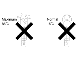
- Observe the permitted temperature (-40°C to 85 °C).
- Prevention of Dust Entry
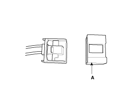
A. Immediately before assembling each unit and in-line connector, remove the dust cap. - Contamination Prevention
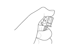
A. Do not touch or contaminate the end face of the ferrule. - Damage Prevention
A. Do not drop or step on. B. Do not pull the cables excessively. - Damage Prevention
A. Do not twist. 
- Observe the allowable bend radius (more than 25°). Do not store in a bent or kinked state.
- Observe the allowable temperature range (-40° to 85°). Observe the storage location and temperature selection.
- Dust prevention: Pack the cables in a polyethylene bag.
- Contamination prevention: Do not store the cables together with other items.
- Damage prevention: Do not place other boxes on the cable box.
- Route the cables with a bend radius of 25° or more (optical damage occurs if the angle is less than 25°).
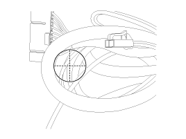
- Maintain the proper temperature when storing the cables. > SPEC (-40° to 85°)
- Remove the dust cap immediately before assembling the device (to prevent dust exposure and contamination from touching).
- Do not touch the end face of the ferrule (water or contaminants can cause optical damage).
- Do not step on the cables (damage to cables and connectors).
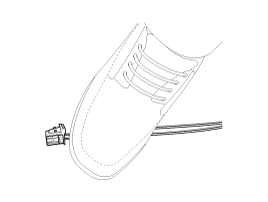
- Do not drop the cables on the floor during routing (damage to connectors).
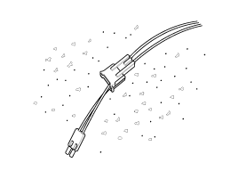
- Do not drag the cables across the floor (damage to cables and connectors).
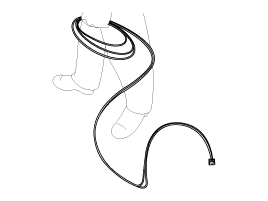
- Do not twist or excessively bend the cables when storing excess length.
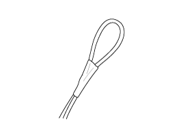
- Do not bend or break the cables at the specified parts, as shown in the illustration, during routing.
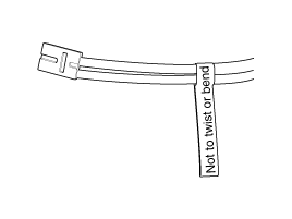
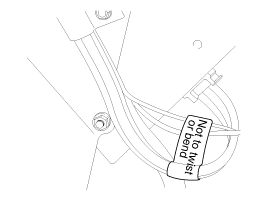
- Do not twist the cables (tension on the cable causes optical output damage).
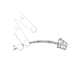
- Do not pull the cables excessively (prevent damage at the cable and connector joint).
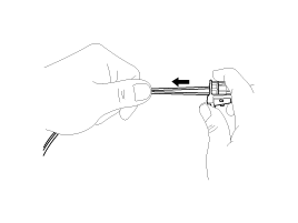
- Do not bend the cable at the end of the connector (to prevent optical output damage from cable bending).
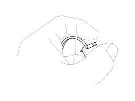
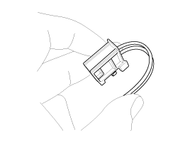
- Purpose: Clean the POF grinding surface when the dust cap is torn or for other reasons (to restore optical damage).
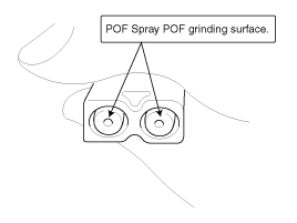
- Method: After disconnecting the cable connector from the device, spray the POF grinding surface with strong dust-removal spray.
- Required tools: Strong dust-removal spray, 1 pc.
- Prepare the tools for the work.
- Disconnect the cable connector from the device.
- Reassemble after spraying strong dust-removal spray onto the POF grinding surface.
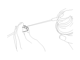
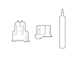
- Purpose: Replace a single connector due to external impact or improper handling.
- Method: Replace the connector after separation by lifting the damaged connector with a repair key.
- Required tools: Repair key 1 EA, one replacement connector.
- Prepare the tools for the work.
- Separate the connector for the block.
- Separate the locked part of the cable connector by lifting it with a repair key.
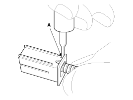
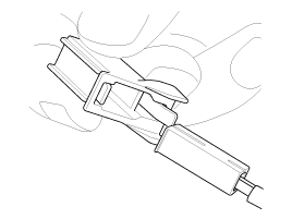
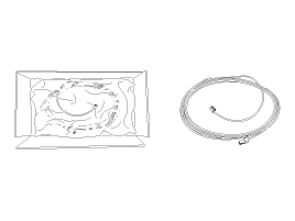
- Purpose: Replace a defective assembly due to scratching, breakage, etc.
- Method: Replace the cable with a new one after removing it from the vehicle body by cutting the cable and removing the damaged cable connector.
- Prepare the tools for the work.
- Disconnect the cable connector from the device.
- Install the new cable assembly after cutting the cable assembly and separating it from the vehicle body. (Re-locking is required.)
| System | Reset | ||||
| Power Up/Down Window |
|
||||
| Panoramic Roof | During opening/closing of the sunroof, if power is not supplied from the battery, the battery is discharged, the corresponding fuse is replaced, or the sunroof is operated with the emergency handle, the sunroof should be initialized as follows.
|

Trip Computer, Clock and Audio Reset: When reconnecting the battery cable after disconnection, recharging a discharged battery, or installing the memory fuse located on the driver's side instrument panel, be sure to reset the systems listed in the table below. Also, when replacing or reinstalling these fuses after removal, they must be reset in accordance with the table below. Please refer to the table below during service.
| System | Reset |
| Trip Computer | When the battery is disconnected and reconnected, the trip computer function settings are initialized. Therefore, explain this information to the customer. |
| Clock | Whenever the battery terminals or related fuses are disconnected, the time in the head unit must be reset. (Refer to the Owner's Manual.) |
| Audio | When the battery is disconnected and reconnected, the customer's radio presets are initialized. Therefore, record the customer's radio presets before service and set the customer's radio presets after service. |
Test yourself
A quick Hyundai Genesis DH quiz: every answer comes with an explanation and a link to the manual page.
Was this page helpful?