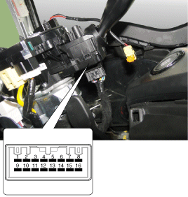
Check each switch position to make sure there is no open circuit between the terminals according to the table below.[LHD]
With switch
Switch Position
Switch Terminal
Resistance (Ω, ±3.5%)
FRONT WIPER INTERMITTENT
FOG
1,9
330
OFF
?
Intermittent (AUTO)
800
Down
1800
High
5700
REAR WIPER INTERMITTENT
OFF
9-16
?
Down
910
High
2910
Intermittent Wiper Volume
Level 1
7~9
330
Level 2
690
Level 3
1310
Level 4
2610
Level 5
7310
Fog Light Switch
OFF
9.10
?
Front Fog Lamps
910
Rear Fog Lamp
2910
Turn Signal Switch
OFF
9.12
?
LEFT
910
LAW
2910
High/Low Beam Switch
OFF
9~13
?
PASSING
910
Headlamps
2910
Switch
OFF
9~14
?
AUTO/DRL
680
Tail Light
1680
Headlamps
5580
[RHD]
With switch
Switch Position
Switch Terminal
Resistance (Ω, ±3.5%)
Wiper Arm
FOG
3-16
330
OFF
?
Intermittent (AUTO)
800
Down
1800
High
5700
REAR WIPER INTERMITTENT
OFF
9-16
?
Down
910
High
2910
Intermittent Wiper Volume
Level 1
2.16
330
Level 2
690
Level 3
1310
Level 4
2610
Level 5
7310
Fog Light Switch
OFF
14~16
?
Front Fog Lamps
910
Rear Fog Lamp
2910
Turn Signal Switch
OFF
13~16
?
LEFT
910
LAW
2910
High/Low Beam Switch
OFF
12~16
?
PASSING
910
Headlamps
2910
Switch
OFF
11-16
?
AUTO/DRL
680
Tail Light
1680
Headlamps
5580
The body electrical system can be quickly diagnosed for defective parts using the Global Diagnostic System (GDS). The GDS provides the following information.
Self-diagnosis: checking and displaying diagnostic trouble codes (DTC)
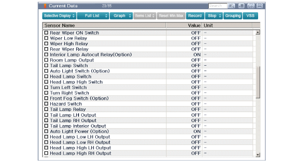
Current data: checks the status of input/output signals.
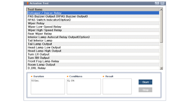
Actuation test: checking the operating conditions of the system
Additional function: control other than operation, such as option setting and zero point adjustment
Select "Vehicle Model" and the system to be checked to inspect the vehicle with the tester.
Select "Body Control Module (BCM)" to check the multifunction switch.
Select the "Current Data" menu to check the current input/output status. The input/output data for sensors related to the multifunction switch can be checked.
To check the DTC of the multifunction switch, select "Diagnostic Trouble Codes".
Verification (with GDS)
?
Test yourself
A quick Hyundai i20 quiz: every answer comes with an explanation and a link to the manual page.