Body Electrical System
Relay Box (Interior) Description and Operation
In this manual: Body Electrical System
6steps
~36min
2/5difficulty
Done 0 of 6
Description
SJB (Smart Junction Box)- Specification
Item Requirement NOTE Rated Voltage 12 V DC X Voltage range 8 ~ 16 V DC Normal operation within this range Storage temperature -40 °C ~ +95 °C X Operating Temperature -30 °C ~ +85 °C X Operating humidity 85% Printed circuit board, moisture insulation, coating, etc. Dark Current Max. 200 µA All loads open Operating Voltage Range 8 ~ 16 V DC Must activate normally within the normal range Maximum humidity 85% Adjusted together with parts requiring insulation, such as printed circuit board, moisture insulation, coating, etc. Insulation resistance There must be no fire caused by short circuits - Rated Load
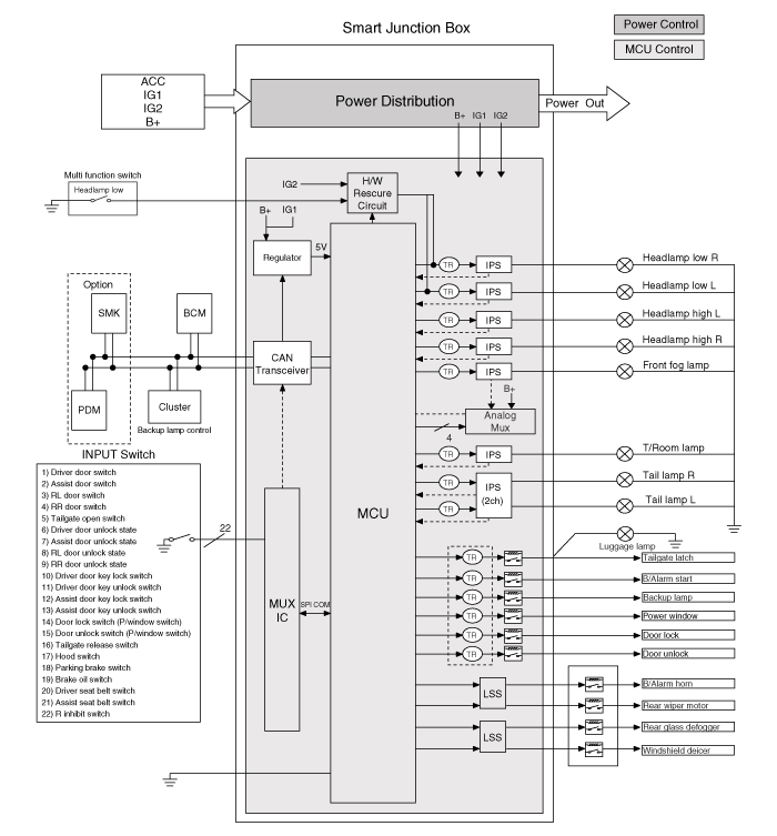
Item Rated Load Low beam headlamp, left 55 W Low beam headlamp, right 55 W High beam headlamp, left 60 W (max.) High beam headlamp, right 60 W (max.) Left Rear Lamp 41 W (max.) Rear combination lamp, right 31 W (max.) Front fog lamp, left + right 54 W Interior Lamp 45 W B/Alarm starter relay coil control 0.9 W RR FOG relay coil control 0.6 W Liftgate latch or luggage compartment lamp (liftgate power) relay coil control 0.6 W Backup relay coil control 0.45 W Rear wiper relay coil control (external) 12 W (max. output) B/Horn relay coil control (external) 12 W (max. output) RR.HTD relay coil control (external) 12 W (max. output) Front de-icer relay coil control (external) 12 W (max. output) - Block Diagram
- Main functions of SJB
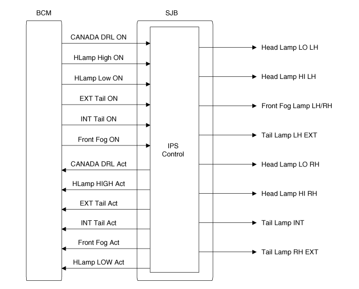
- Lamp control and wire protection through IPS.
- When the reference voltage is exceeded, normal PWM voltage control prevents loss or damage of the lamp.
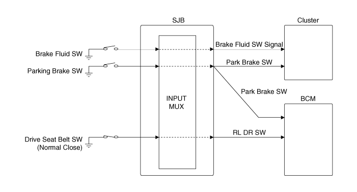
- CAN output for switching signal input.
- Diagnosis by CAN (short to ground, open circuit)
- Fail-safe lamp control.
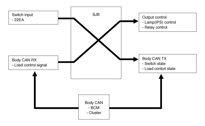
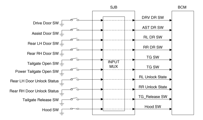
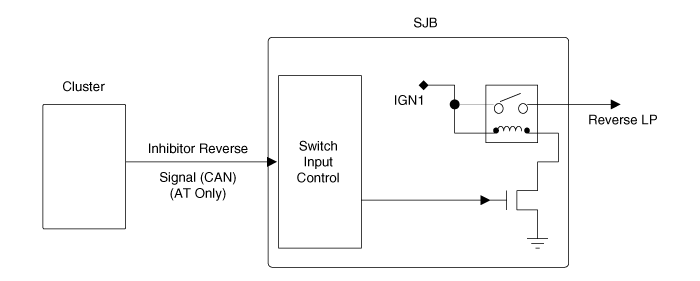
NO Section Contents 1 Input SW Receives switch input and sends switch status as a CAN message to each module. 2 Lamp Control (IPS) Receives commands from the BCM as a CAN message to control lamps via IPS 3 Internal Relay Control Receives commands from the BCM as a CAN message and controls relays in the IP Box T / Gate Latch, B / Alarm Start, Back-up, Rear Fog Lamp 4 External Relay Control Receives commands from the BCM as a CAN message and controls relays outside the IP Box B / Horn, Rear Wiper Motor, Rear Heater, Front Anti-Icer 5 Low Power Consumption Mode
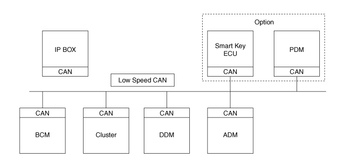
(Sleep Mode)When the CAN message or switch input does not change for 5 seconds, the unit enters low power consumption mode (sleep mode). 6 Wake-up Mode When a CAN message or switch input changes in low power consumption mode, the unit returns to normal mode. 7 Output Status Transmission Output status of lamps and rear fog lamps is sent to the BCM as a CAN message 8 HW Fail-Safe When the MCU fails and the headlamp low beam switch is turned on, the headlamp low beam is activated. - Network
- CAN Input and Output Flow
Test yourself
A quick Hyundai Tucson LM quiz: every answer comes with an explanation and a link to the manual page.
Was this page helpful?