Body Electrical System
Relay Box (Engine Compartment) Repair Procedures
In this manual: Body Electrical System
11steps
~66min
3/5difficulty
Done 0 of 11
Inspection
- Disconnect the negative (-) battery terminal.
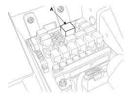
- Remove the relay from the engine room relay box.
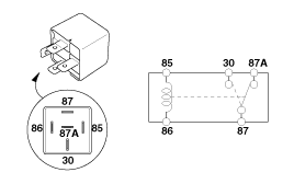
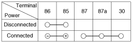
- There should be continuity between terminals No. 30 and No. 87 when battery voltage and ground are applied to terminals No. 85 and No. 86.
- There should be no continuity between terminals No. 30 and No. 87 when battery voltage is disconnected.
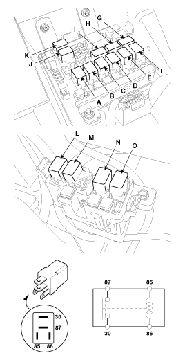
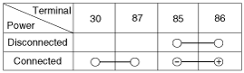
- There should be continuity between terminals No. 30 and No. 87 when battery voltage and ground are applied to terminals No. 85 and No. 86.
- There should be continuity between terminals No. 30 and No. 87 when the power is off.
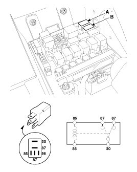
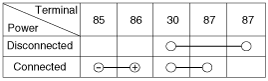
- There should be continuity between terminals No. 30 and No. 87 when battery voltage and ground are applied to terminals No. 85 and No. 86.
- There should be no continuity between terminals No. 30 and No. 87 when battery voltage is disconnected.
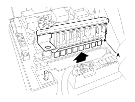
- Make sure that there is no play in the fuse holders and that the fuses are securely installed.
- Is the rating of the fuse specified correctly for each circuit?
- Check for blown fuses. If a fuse must be replaced, always use a new fuse of the same capacity. Always determine why the fuse blew first and fully resolve the problem before installing a new fuse.
|

Test yourself
A quick Hyundai Tucson LM quiz: every answer comes with an explanation and a link to the manual page.
Was this page helpful?