Engine Installation
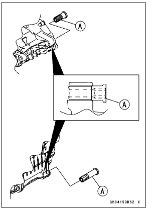
- Apply molybdenum disulfide grease to the threads of the adjusting collars [A].
- Install the adjusting collars to crankcase backside until end of the threads.
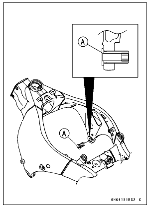
- Install the adjusting collar [A] to the frame until end of the threads.
- Replace the engine mounting nuts with new ones.
- Support the engine with a suitable stand.
Put a plank onto the suitable stand for engine balance.
Support the engine until all bolts have been tightened.
- Install the engine mounting bolts and nuts, following the specified installing sequence.
First, install and tighten the following bolts temporarily.
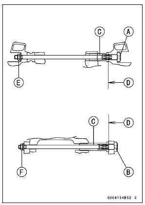
Middle Engine Mounting Bolt [A] Lower Engine Mounting Bolt [B] Left Front Engine Mounting Bolt [C] Right Front Engine Mounting Bolt [D]

Second, tighten the left front engine mounting bolt [A].
Frame [B] Engine [C] Torque - Left Front Engine Mounting Bolt: 44 NВ·m (4.5 kgfВ·m, 32 ftВ·lb)
Third, insert the middle [A] and lower [B] engine mounting bolts to the adjusting collars [C], and tighten the bolts counterclockwise.
NOTE
Tighten the bolts until the clearance [D] between the frame and collar come to 0 mm (0 in.).
Torque - Middle Engine Mounting Bolt: 9.8 NВ·m (1.0 kgfВ·m, 87 inВ·lb) Lower Engine Mounting Bolt: 9.8 NВ·m (1.0 kgfВ·m, 87 inВ·lb)
Fourth, tighten the middle [E] and lower [F] engine mounting nuts.
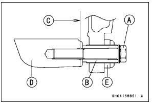
Fifth, remove the right front engine mounting bolt [A].
Sixth, tighten the adjusting collar [B] clockwise by hand until the clearance [C] between the engine [D] and collar come to 0 mm (0 in.).
Seventh, tighten the adjusting collar locknut [E].
Special Tool - Engine Mount Nut Wrench: 57001-1450
Torque - Adjusting Collar Locknut: 49 NВ·m (5.0 kgfВ·m, 36 ftВ·lb)
Lastly, tighten the right front engine mounting bolt.
Torque - Right Front Engine Mounting Bolt: 44 NВ·m (4.5 kgfВ·m, 32 ftВ·lb)
- Run the leads, cables and hoses correctly (see Cable, Wire, and Hose Routing section in the Appendix chapter).
- Install the removed parts (see appropriate chapters).
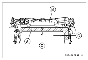
Check that the pad [A] is in place on the heat insulation plate [B].
5 mm (0.20 in.) [C]
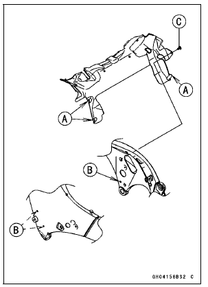
Insert the projections [A] into the holes [B].
Apply a non-permanent locking agent to the threads of the heat insulation plate bolt [C] and tighten it.
- Adjust: Throttle Cables (see Throttle Control System Inspection in the Periodic Maintenance chapter) Clutch Cable (see Clutch Operation Inspection in the Periodic Maintenance chapter) Drive Chain (see Drive Chain Slack Inspection in the Periodic Maintenance chapter)
- Fill the engine with engine oil (see Engine Oil Change in the Periodic Maintenance chapter).
- Fill the engine with coolant (see Coolant Change in the Periodic Maintenance chapter).
Test yourself
A quick Kawasaki Ninja ZX-10R quiz: every answer comes with an explanation and a link to the manual page.