Brake System
Electric Parking Brake (EPB) Schematic Diagrams
In this manual: Brake System
~1min read
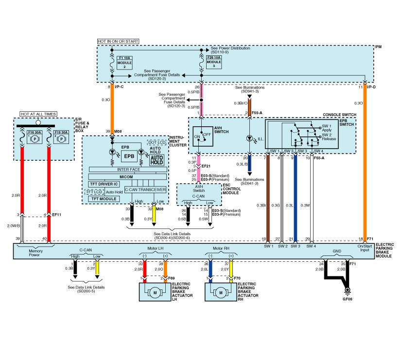
EPB Circuit Diagram
EPB Connector Input/Output
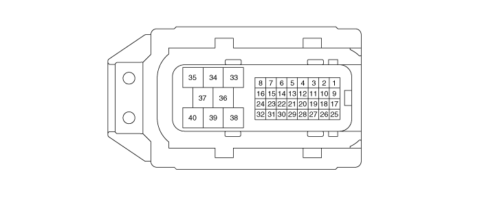
| Pin No. | Description |
| 1 | CAN_High |
| 2 | CAN Low |
| 18 | IGN (+) |
| 19 | EPB Switch Signal 1 |
| 21 | EPB Switch Signal 3 |
| 27 | EPB Switch Signal 2 |
| 29 | EPB Switch Signal 4 |
| 33 | Rear LH Motor (-) |
| 34 | Ground |
| 35 | Ground |
| 36 | Rear RH Motor (-) |
| 37 | Rear RH Motor (+) |
| 38 | Rear LH Motor (+) |
| 39 | Battery (Rear RH Motor) |
| 40 | Battery (Rear LH Motor) |
Test yourself
A quick Kia Cadenza VG Owner's Manual quiz: every answer comes with an explanation and a link to the manual page.
Was this page helpful?