Body Electrical System
Schematic Diagrams
In this manual: Body Electrical System
~2min read
Wiring Diagram
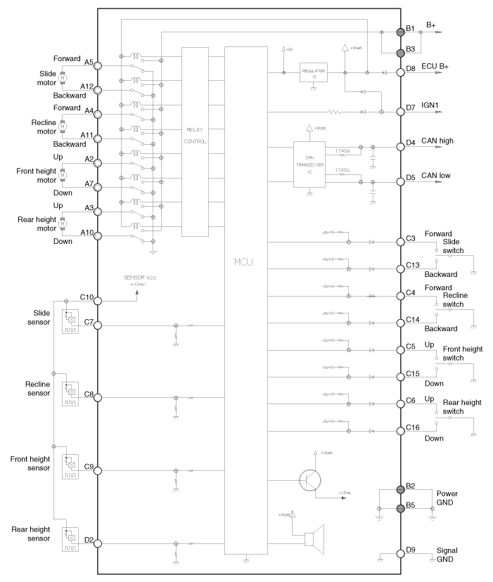
Input/Output Specification
Connector Pin Layout

| No | Signal Name | Input/Output | Contents | NOTE |
| A1 | - | - | - | |
| A2 | FR Height Motor Up | or | FR Height Motor Up Output | |
| A3 | RR Height Motor Up | or | RR Height Motor Up Output | |
| A4 | FR Tilt Motor | or | FR Tilt Motor Output | |
| A5 | FR Slide Motor | or | FR Slide Motor Output | |
| A6 | - | - | - | |
| A7 | FR Height Motor Down | or | FR Height Motor Down Output | |
| A8 | - | - | - | |
| A9 | - | - | - | |
| A10 | RR Height Motor Down | or | RR Height Motor Down Output | |
| A11 | RR Tilt Motor | or | RR Tilt Motor Output | |
| A12 | RR Slide Motor | or | RR Slide Motor Output | |
| B1 | Ground (Power) | I | Power B+ for Operating Motor | |
| B2 | Ground (Power) | I | Ground GND for Operating Motor | |
| B3 | B+ (Power) | I | Power B+ for Operating Motor | |
| B4 | - | - | - | |
| B5 | Ground (Power) | I | Ground GND for Operating Motor | |
| C1 | - | - | - | |
| C2 | - | - | - | |
| C3 | FR Slide Manual Switch | I | FR Slide Manual Switch Input | ON: Ground |
| C4 | FR Tilt Manual Switch | I | FR Tilt Manual Switch Input | ON: Ground |
| C5 | FR Height Manual Switch | I | FR Height Manual Switch Input | ON: Ground |
| C6 | RR Height Manual Switch | I | RR Height Manual Switch Input | ON: Ground |
| C7 | Slide Motor Sensor | I | Slide Motor Sensor Input | Pulse Signal |
| C8 | Tilt Motor Sensor | I | Engine tilt sensor input | Pulse Signal |
| C9 | FR height sensor (engine) | I | FR height sensor input | Pulse Signal |
| C10 | Seat Vcc sensor | or | VCC for operating sensor | 5V |
| C11 | - | - | - | |
| C12 | - | - | - | |
| C13 | RR slide manual switch | I | RR slide manual switch input | ON: GROUND |
| C14 | Seatback recline manual switch | I | RR recline manual switch input | ON: GROUND |
| C15 | FR height DOWN manual switch | I | FR height DOWN manual switch input | ON: GROUND |
| C16 | RR height DOWN manual switch | - | RR height DOWN manual switch input | ON: GROUND |
| C17 | - | - | - | |
| C18 | - | - | - | |
| C19 | - | - | - | |
| C20 | - | - | - | |
| D1 | SET switch | or | SET switch | |
| D2 | RR height sensor | I | RR height lift sensor | Pulse Signal |
| D3 | Switch 1 | or | IMS 1 switch | |
| D4 | CAN High | Input/Output | CAN | |
| D5 | CAN Low | Input/Output | CAN | |
| D6 | Switch 2 | or | IMS 2 switch | |
| D7 | IGN1 | I | IGN1 input | BAT |
| D8 | B+ (ECU) | I | ECU power supply input | BAT |
| D9 | Ground (ECU) | I | ECU GROUND | |
| D10 | - | - | - | |
| D11 | - | - | - | |
| D12 | - | - | - | |
| D13 | - | - | - | |
| D14 | - | - | - | |
| D15 | - | - | - | |
| D16 | - | - | - |
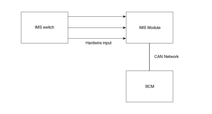
Communication system
Test yourself
A quick Kia Optima Hybrid Owner's Manual quiz: every answer comes with an explanation and a link to the manual page.
Was this page helpful?