Block DiagramThe LDWS consists of the following units
No
Item
Function
Position
1
LDWS UNIT
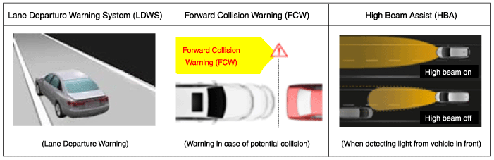
Lane Departure Warning System (LDWS): Recognizes the lane ahead and activates the warning function if the vehicle is in danger of leaving the roadway.
FCW: Monitors the area ahead of the vehicle and activates the warning function if the vehicle is in danger of a collision.
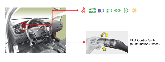
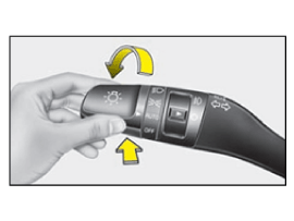
High Beam Assist (HBA): Detects the headlights and taillights of vehicles ahead and turns the high beams on/off.
SLIF (Speed Limit Information Function): Detects road signs with the camera and displays speed limit information using navigation map data.
Windshield
2
LDWS switch
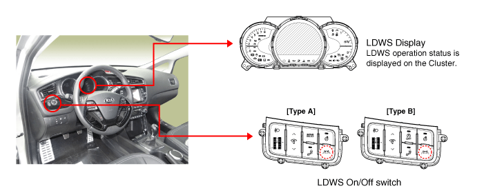
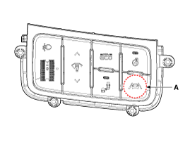
LDWS ON/OFF switch
Airbag Location (Left)
3
Multifunction switch
HBA On/Off Switch (MF: Automatic Mode)
Steering Wheel
4
User Settings Menu
SLIF On/Off, FCW On/Off Menu
Cluster Menu
5
Cluster/Buzzer
SLIF/FCW/LDWS Fading
Cluster
※ Europe: (LDWS/SLIF) / China, Middle East, Australia: (LDWS) The LDWS camera unit processes the following functions using the video signal input.
Lane detection and analysis
Detect light from the vehicle ahead
Detects and analyzes the status of the vehicle ahead and sounds a warning (or displays a message) to the driver when necessary.
Transmits information using high-speed CAN communication
Lane Departure Warning System (LDWS) UnitThe Lane Departure Warning System is a convenient device that recognizes the lanes ahead using the camera image and vehicle signal information, and alerts the driver if the vehicle deviates from the lane. It consists of a camera and recognizes the lane by calculating the camera input image signal. The sensor module processes the image and determines the lane ahead. The camera unit determines the lane and calculates the main parameters, i.e., the vehicle center offset, road width, vehicle yaw angle and road curvature, to keep the lane. The following procedures relate to lane recognition through image processing.
Ground Sensing in Road Image Input Procedure
Lane Filtering Calculation
Lane Candidate Point Extraction (Constituent points evaluated as lane)
Ground Sensing Using Candidate Points
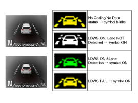
LDWS Operation Process When the LDWS switch is pressed, the Lane Departure Warning System (LDWS) operating state is displayed in the center while the LDWS lamp is on. The specific classification of displays is shown in the following table.
Category
Operation
LDWS Display and Warning
Control (Button)
On
LDWS ON
Off
LDWS OFF
Operation Status
Cluster Indicator
Operating Conditions
Activated when the vehicle speed exceeds the set speed while the LDWS is turned on.
[Start: 60 km/h ↑] [Stop: 55 km/h ↓]
※ The Lane Departure Warning is not activated when the turn signal or hazard lamp is on.
FCWS Operation Process
Category
Operation
LDWS Display and Warning
Control (USM)
On
FCW ON
Off
FCW OFF
Operation Status
Displayed only when the alarm is turned on
Operating Conditions
Activated when the vehicle speed exceeds the set speed while the FCW is turned on.
[Start: 40 km/h ↑] [Stop: 35 km/h ↓]
FCW Display
FCWS control switch: consists of the User Settings Menu (USM)
High Beam Assist (Multifunction Switch in "AUTO/HIGH BEAM" Position)
Category
Operation
LDWS Display and Warning
Control (Button)
On
When the high beam switch is turned on (push-return) with the multifunction switch set to AUTO.
HBA ON + Low Beam HBA ON + High Beam
Off
When the high beam switch is activated again when the multifunction switch is NOT set to AUTO or when HBA is turned on.
Operation Status
LCD Display
Operating Conditions
Activated when the vehicle speed exceeds the set speed while HBA is turned on.
[Start: 40 km/h ↑] [Stop: 35 km/h ↓]
※ Activated only when the multifunction switch is set to "AUTO" and the low beam is on.
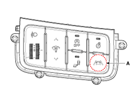
LDWS On/Off Switch (A) When the LDWS switch is pressed, LDWS is turned on and the LDWS indicator illuminates. When the switch is pressed again, LDWS is turned off and the indicator goes off.
[Enter]
[Type B]
Automatic high beam control switch: The automatic high beam control system is activated when the multifunction light switch is set to AUTO and the Light SW is set to the high beam position (pressed).
If the light switch is not set to the AUTO position or the high beam position, the automatic high beam control system is turned off.
LDWS Warning Method
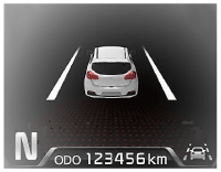
Visual warning: the lane in the direction of departure is marked in yellow.
The LDWS switch must be turned on. The LDWS lamp on the instrument panel illuminates when the switch is on.
It operates when the LDWS is set and the vehicle speed exceeds 60 km/h. The warning function is temporarily suspended when the vehicle speed is below 60 to 55 km/h, and the warning restarts when the speed exceeds 60 km/h (37 mph).
If the driver turns on both the left and right turn signals to indicate an intention to change lanes, the warning will not activate regardless of the direction of lane departure. The lane departure warning function restarts 2 seconds after the left and right turn signals are turned off. No warning will be given when the hazard warning lamps are on.
Turn on the turn signal before changing lanes. Changing lanes without turning on the turn signal generates a warning.
The warning is released when the vehicle detects a lane change departure exceeding 40% of the vehicle body crossing the lane.
The lane departure warning does not activate when the vehicle is driven in the center of the lane.
LDWS Operating Conditions. The LDWS operating conditions are as follows.
?
Test yourself
A quick Kia Cee'd quiz: every answer comes with an explanation and a link to the manual page.