Theft-deterrent control module inspection
1. Remove the theft-deterrent control module without disconnecting the connectors.
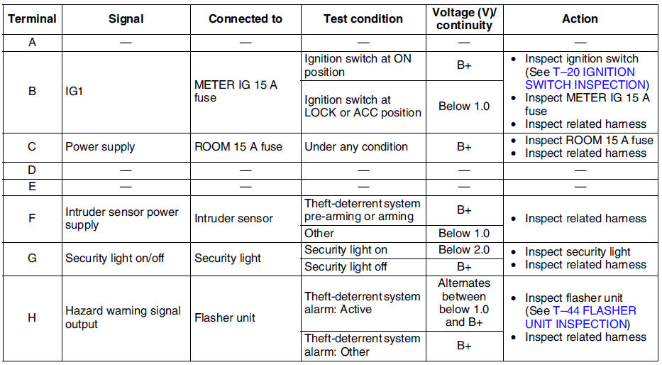
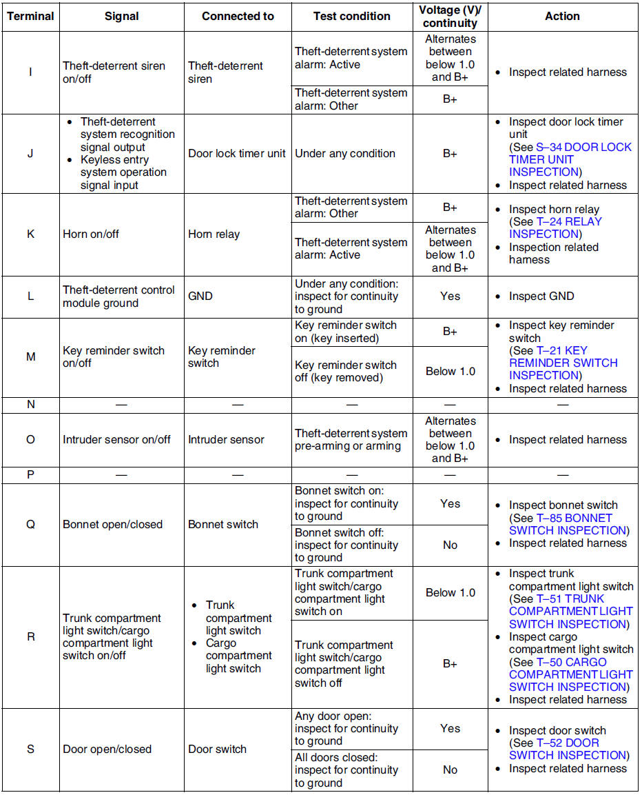
2. Measure the voltage at the theft-deterrent control module terminals as indicated below.
3. Disconnect the theft-deterrent control module connector before inspecting for continuity at terminals L, Q, S, T, and V.
4. If not as specified, inspect the parts listed under Action.
- If the parts and wiring harnesses are okay but the system still does not work properly, replace the theft-deterrent control module.

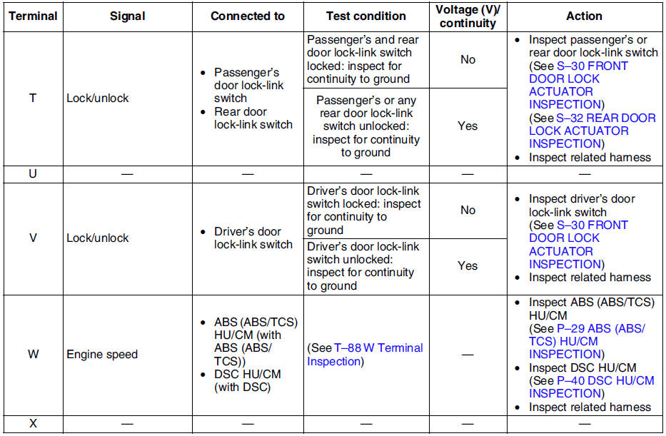
W Terminal Inspection 1. Connect SST
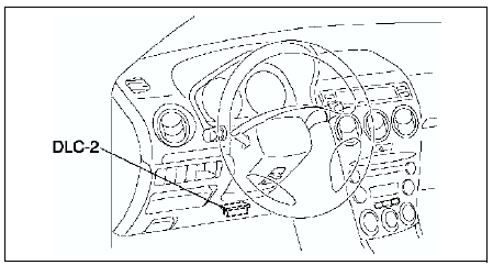
(WDS or equivalent) to the vehicle DLC-2 16-pin connector.
2. Access and monitor RPM of PID using SST (WDS or equivalent).
- If engine speed signal normal, go to next step.
- If engine speed signal abnormal, inspect the ABS (ABS/TCS) HU/CM, DSC HU/CM and related wiring harness.
3. Inspect for continuity between the ABS (ABS/TCS) HU/CM terminal X and the theft-deterrent control module terminal W, or DSC HU/CM terminal AB and the theft-deterrent control module terminal W using an ohmmeter.
- If not continuity, replace the related wiring harness.
- If wiring harness is normal, replace the theft-deterrent control.
Test yourself
A quick Mazda 6 quiz: every answer comes with an explanation and a link to the manual page.