Diagnosis and Repair Workflow
Work Flow
OVERALL SEQUENCE
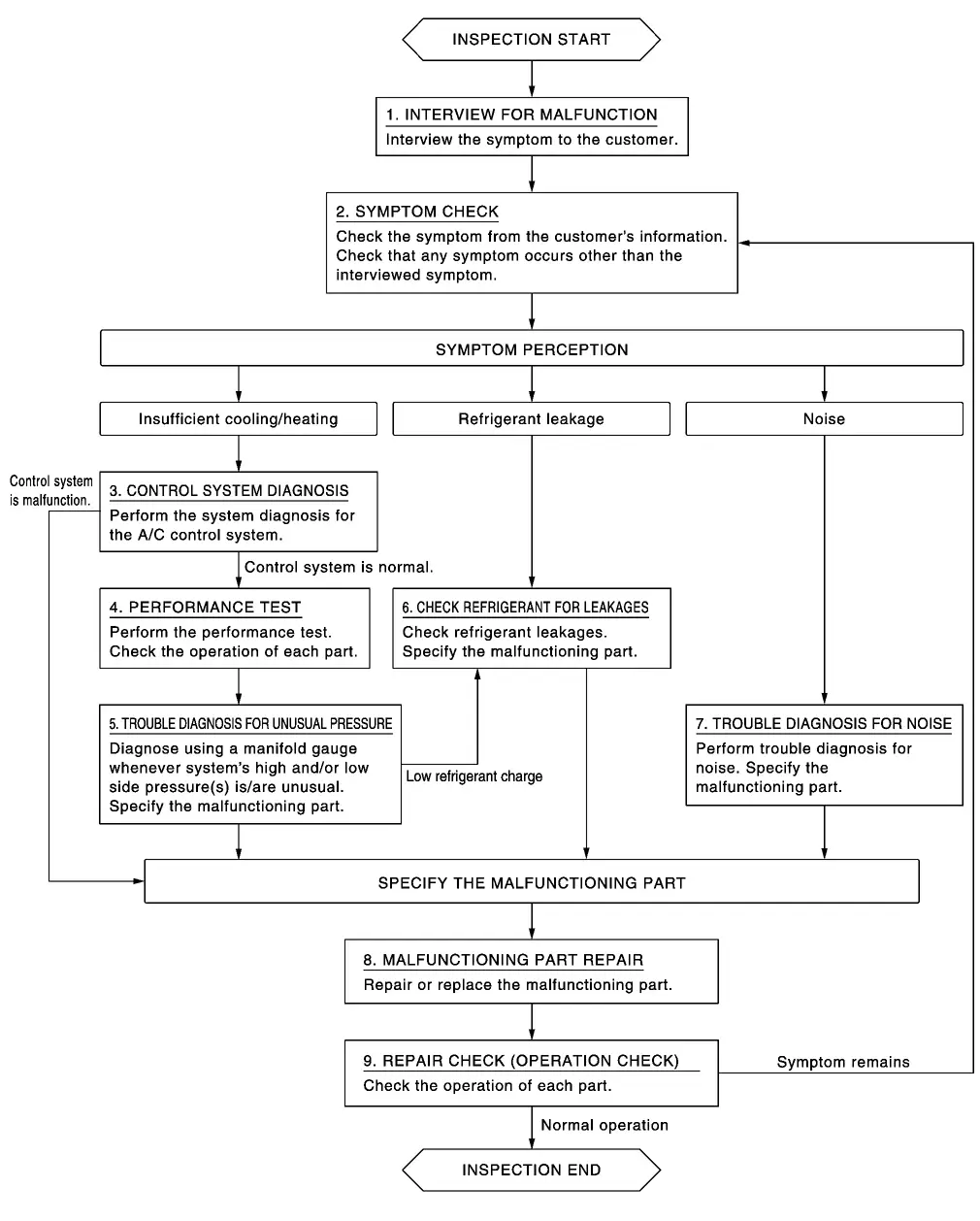
DETAILED FLOW
INTERVIEW FOR MALFUNCTION
Interview the symptom to the customer.
>>GO TO 2.
SYMPTOM CHECK
Check the symptom from the customer's information. Check that any symptom occurs other than the interviewed symptom.
Insufficient cooling/heating>>GO TO 3.
Refrigerant leakage>>GO TO 6.
Noise>>GO TO 7.
CONTROL SYSTEM DIAGNOSIS
Perform the system diagnosis for the A/C control system. Refer to Work Flow.
Is A/C control system normal?
YES>>GO TO 4.
NO>>GO TO 8.
PERFORMANCE TEST
Perform the performance test. Check the operation of each part. Refer to Inspection.
>>GO TO 5.
TROUBLE DIAGNOSIS FOR UNUSUAL PRESSURE
Diagnose using a manifold gauge whenever system's high and/or low side pressure(s) is/are unusual. Specify the malfunctioning part. Refer to Symptom Table.
Low refrigerant charge>>GO TO 6.
Except above>>GO TO 8.
CHECK REFRIGERANT FOR LEAKAGES
Check refrigerant for leakages. Specify the malfunctioning part. Refer to Leak Test.
>>GO TO 8.
TROUBLE DIAGNOSIS FOR NOISE
Perform trouble diagnosis for noise. Specify the malfunctioning part. Refer to Symptom Table.
>>GO TO 8.
MALFUNCTION PART REPAIR
Repair or replace the malfunctioning part.
>>GO TO 9.
REPAIR CHECK (OPERATION CHECK)
Check the operation of each part.
Does it operate normally?
YES>>INSPECTION END
NO>>GO TO 2.