Evap Canister
Exploded View
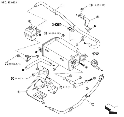
 |
Vent hose 1 |  |
Canister filter |  |
Bracket 3 |
 |
EVAP canister |  |
Vent hose 2 |  |
Bracket 1 |
 |
Vent hose 3 |  |
EVAP canister vent control valve |  |
Clip |
 |
EVAP control system pressure sensor |  |
Bracket 2 |  |
Vent hose 4 |
 |
Clamp | ||||
 |
To fuel tank. Refer to FUEL TANK : Exploded View. |  |
To engine. Refer to Hydraulic Layout. | ||
| : vehicle front | |||||
 |
: Always replace after every disassembly. | ||||
 |
: N·m (kg-m, ft-lb) | ||||
 |
: Should be lubricated with oil. | ||||
 , ,  ,  : Indicates that the parts is connected at points with same symbols in actual vehicle. |
|||||
Hydraulic Layout

|
EVAP canister purge volume control solenoid valve | |
EVAP resonator | |
EVAP line |
|
Fuel line | |
Fuel tank | |
Fuel filler neck |
|
EVAP canister |
Removal & Installation
REMOVAL
EVAP canister
Remove spare tire. Refer to Removal & Installation.
Disconnect EVAP control system pressure sensor harness connector and vent hose 4 from EVAP canister .
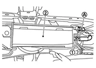
Disconnect EVAP canister vent control valve harness connector and vent hose 1 from EVAP canister .

Hold the sides of connector, push in tabs and pull out vent tube.
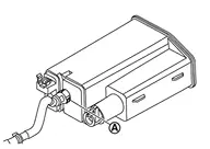
Remove mounting bolt and mounting nut of bracket 1, and remove bracket 1 and EVAP canister as a set from the vehicle
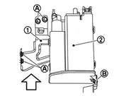
| : vehicle front |
Remove EVAP canister from bracket 1.
Canister filter
Remove vent hose 1 and vent hose 2 from canister filter .

Remove canister filter from b racket 3.
Remove vent hose 1 and vent hose 2 from the vehicle if necessary.
INSTALLATION
Install in the reverse order of removal.
Disassembly and Assembly
DISASSEMBLY
Disengage the pawl and turn EVAP canister vent control valve counterclockwise.
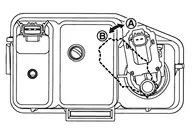
|
: Lock |
|
: Unlock |
Remove the EVAP canister vent control valve.
ASSEMBLY
Assemble in the reverse order of disassembly.
Inspection
Check EVAP canister as per the following:
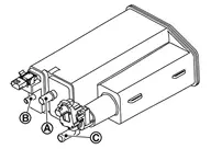
Block port .
Blow air into port and check that it flows freely out of port  .
Release blocked port .
Apply vacuum pressure to port and check that vacuum pressure exists at the ports and .
Block port and .
Apply pressure to port and check that there is no leakage.