Fuel Level Sensor Unit, Fuel Filter and Fuel Pump Assembly
Exploded View
REMOVAL
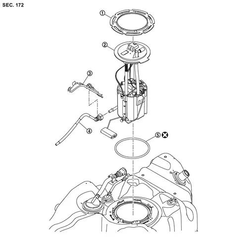
 |
Lock ring |  |
Fuel level sensor unit, fuel filter and fuel pump assembly |  |
Transfer tube bracket |
 |
Transfer tube |  |
O-ring | ||
 |
: Always replace after every disassembly. | ||||
DISASSEMBLY
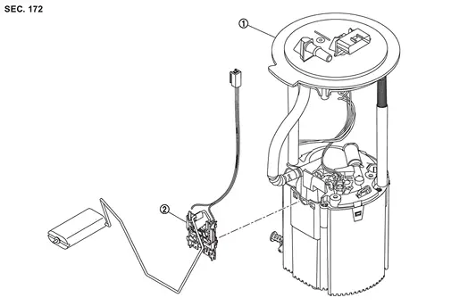
|
Fuel filter and fuel pump assembly | |
Fuel level sensor unit |
Removal & Installation
REMOVAL
Check fuel level on a level ground. If the fuel level is 7/8 of the fuel tank (full or nearly full), draw appropriate amount of fuel from the fuel tank.
| Guideline | : Draw approximately 20 liters (5-2/8 us gal, 4-3/8 Imp gal) from a full-tank condition. |
In the event of fuel pump malfunction, first insert the filler tube guide [service setting part: 17261 6RA0A] into the filler port,then insert a 16 mm (0.63 in) diameter hose into the filler tube guide andpump approximately 20 liters (5-2/8 us gal, 4-3/8 Imp gal) fuel.
Release the fuel pressure from the fuel lines. Refer to Work Procedure.
Open fuel filler lid.
Insert a general purpose pipe with the dimensions shown in fuel filler cap less unit and release the pressure inside the fuel tank.
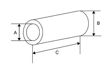
| A | : Over Φ 16 mm (0.63 in) |
| B | : Φ 21.0 mm (0.83 in) |
| C | : 150 mm (5.91 in) |
Remove LH side of the second seat.Refer to following :
CAPTAIN SEAT : Refer to Removal and Installation.
BENCH SEAT : Refer to Removal and Installation.
Peel off floor carpet, then remove inspection hole cover by turning clips clockwise by 90 degrees  .
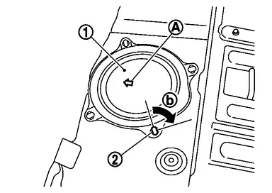
 |
: vehicle front mark |
Disconnect harness connector and fuel feed tube .
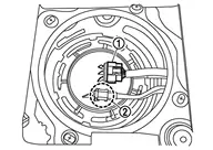
Disconnect quick connector as follows:
Hold the sides of connector, push in tabs and pull out fuel feed tube.
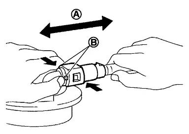
: Pull 
: Push in tabs If quick connector sticks to tube of main fuel level sensor unit, push and pull quick connector several times until they start to move. Then disconnect them by pulling.
Remove lock ring for fuel level sensor unit, fuel filter and fuel pump assembly with unified fuel lock ring wrench [SST: KV101207S0 ( — )] (A) or fuel tank lock ring wrench [SST: KV10119800 ( — )] .
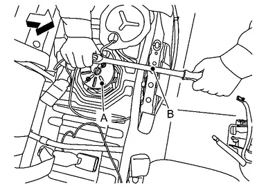
| : vehicle front | |
| B | : Spinner handle |
Remove fuel level sensor unit, fuel filter and fuel pump assembly.
INSTALLATION
Note to the following, and install in the reverse order of removal.
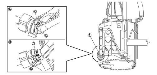
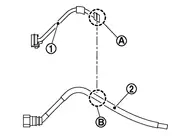
Align the connection positions and of the fuel pump and transfer tube , and insert them straight until click sound.
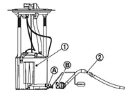
Pull on the fuel pump and transfer tube to make sure they are securely connected.
Install the transfer tube and transfer tube bracket, paying attention to the following.Install the transfer tube and transfer tube bracket in the following order.
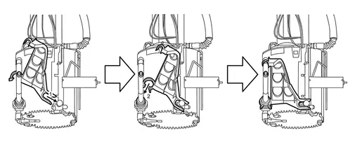
 of the transfer tube bracket and the groove part
 fit securely.
|
: Upper side |
|
: Lower side |
of transfer tube bracket with bellows part of transfer tube . 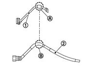 of transfer tube bracket with flat part of transfer tube .
Insert transfer tube while bending the bellows part by hand to make it easier to insert the fuel pump into the fuel tank.

Quick Connector
Connect quick connector as follows:
Check the connection for damage or any foreign materials.
Align the connector with the tube, then insert the connector straight into the tube until a click sound is heard.
After connecting, check that the connection is secure by following method.
Pull the tube and the connector to check they are securely connected.
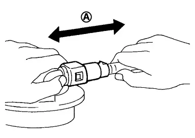
: Pull Visually confirm that the two retainer tabs are connected to the connector.
Inspection
INSPECTION AFTER INSTALLATION
Use the following procedure to check for fuel leakage.
Ignition switch “ON” (with engine stopped), then check connections for leakage by applying fuel pressure to fuel piping.
Start engine and let it idle and check there are no fuel leakage at the fuel system connections.