Rear Wheel Hub and Housing
Exploded View
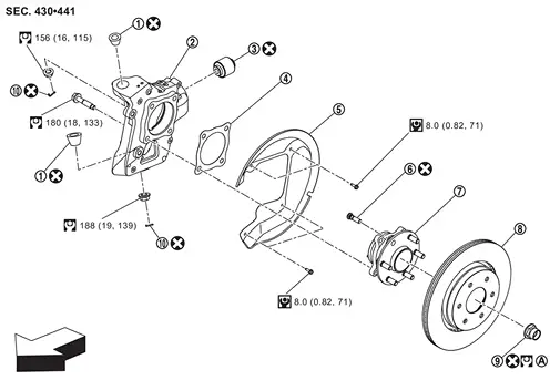
 |
Ball seat |  |
Axle housing |  |
Bushing |
 |
Baffle |  |
Back plate |  |
Hub bolt |
 |
Wheel hub and bearing assembly |  |
Disc rotor |  |
Wheel hub lock nut |
 |
Cotter pin | ||||
 |
Tightening must be done following the installation procedure. Refer to Removal and Installation. | ||||
 |
: vehicle front | ||||
 : N·m (kg-m, ft-lb) |
|||||
 : Always replace after every disassembly. |
|||||
Removal and Installation
WITHOUT DYNAMIC DIGITAL SUSPENSION AND ELECTRONIC AIR SUSPENSION
Removal
Remove tires. Refer to ROAD WHEEL TIRE : Removal & Installation.
Remove brake hose bracket from suspension arm. Refer to Removal and Installation.
Remove caliper assembly. Hang caliper assembly in a place where it will not interfere with work. Refer to Removal and Installation.
Remove disc rotor.
Remove wheel sensor harness. Refer to Removal and Installation.
Put matching mark on drive shaft and wheel hub and bearing assembly.

Using lock nut chisel [SST: KV40108800 ( − )] (A), release stacked area of wheel hub lock nut.
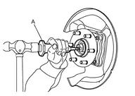
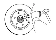
Loosen wheel hub lock nut, using a hub lock nut wrench [SST: KV40104001 (NI-53385)] (A).

Set suitable jack under rear lower link.
Remove rear lower link and coil spring. Refer to Removal and Installation.
Using jack to front lower link.
Loosen the front lower link frame side bolt.
Remove cotter pin and nut, and remove front lower link from axle housing.
Remove cotter pin and nut, and remove suspension arm from axle housing.
Patch wheel hub lock nut with a piece of wood. Hammer the wood to disengage wheel hub and bearing assembly from drive shaft. Take out the wheel hub lock nut.
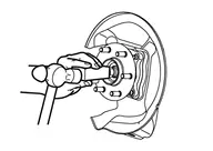
Remove wheel hub and bearing assembly.
Remove axle housing.
Remove back plate from axle housing.
Remove hub bolts from wheel hub and bearing assembly, using the ball joint remover (commercial service tool) (A).

Perform inspection after removal. Refer to Inspection.
Installation
Note the following, and install in the reverse order of removal.
Place a washer
as shown in the figure to install the hub bolts by using the tightening force of the nut  .
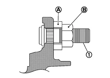
Clean the matching surface of wheel hub lock nut and wheel hub and bearing assembly.
Clean the matching surface of drive shaft and wheel hub and bearing assembly. And then apply paste [service parts (440037S000)] to surface
of joint sub-assembly of drive shaft.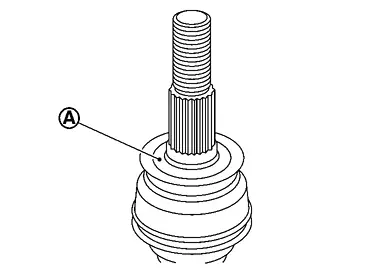
Amount paste 1.0 – 3.0 g (0.04 – 0.10 oz) When installing drive shaft to wheel hub, never align drive shaft staked area
and one of hub bolts .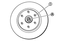
Use the following torque range for tightening the wheel hub lock nut.
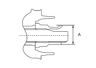
: 218 – 223 N·m Using lock nut crimp punch [SST: KV40108700 ( − )] (A), stake wheel hub lock nut and drive shaft staked area.
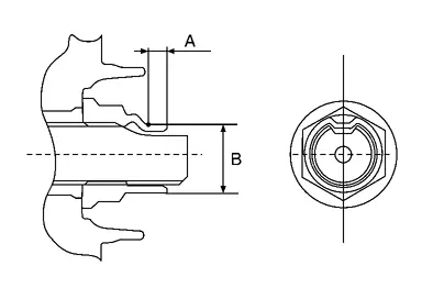
A : 6.2 mm (0.244 in) B : 29.4 – 30.8 mm (1.157 – 1.213 in) Perform the final tightening of each of parts under unladen conditions, which were removed when removing wheel hub and bearing assembly and axle housing.
Perform inspection after installation. Refer to Inspection.
WITH DYNAMIC DIGITAL SUSPENSION AND ELECTRONIC AIR SUSPENSION
Removal
Start engine.
Turn Auto height mode control switch to ON, shift the shift position to N and set to normal height.
Turn OFF the electronic air suspension function. Refer to Operation.
Stop engine.
Lift up the vehicle.
Remove rear tire. Refer to ROAD WHEEL TIRE : Removal & Installation.
Remove brake hose bracket from suspension arm. Refer to Removal and Installation.
Remove caliper assembly. Hang caliper assembly in a place where it will not interfere with work. Refer to Removal and Installation.
Remove disc rotor.
Never drop disc rotor.
Remove wheel sensor harness. Refer to Removal and Installation.
Put matching mark on drive shaft and wheel hub and bearing assembly.
Using lock nut chisel [SST: KV40108800 ( − )] (A), release stacked area of wheel hub lock nut.
Loosen wheel hub lock nut, using a hub lock nut wrench [SST: KV40104001 (NI-53385)] (A).
Support the rear lower link with suitable jack (A) until most horizontal angle with vehicle on the ground.
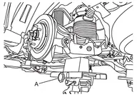
Loosen the air connector and perform air bleeding.
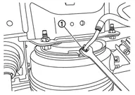
Remove air tube together with air connector from air spring .
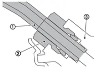
Loosen rear lower link mounting nuts (frame side). Refer to Removal and Installation.
Remove rear lower link from axle housing. Refer to Removal and Installation.
Using jack to front lower link.
Loosen the front lower link frame side bolt.
Remove cotter pin and nut, and remove front lower link from axle housing.
Remove cotter pin and nut, and remove suspension arm from axle housing.
Patch wheel hub lock nut with a piece of wood. Hammer the wood to disengage wheel hub and bearing assembly from drive shaft. Take out the wheel hub lock nut.
Using lock nut crimp punch [SST: KV40108700 ( − )] (A), stake wheel hub lock nut and drive shaft staked area.
Remove wheel hub and bearing assembly.
Remove axle housing.
Remove back plate from axle housing.
Remove hub bolt from wheel hub and bearing assembly, using the ball joint remover (commercial service tool) (A).
Perform inspection after removal. Refer to Inspection.
Installation
Place a washer as shown in the figure to install the hub bolts by using the tightening force of the nut .
Install back plate to axle housing.
Install axle housing.
Install wheel hub and bearing assembly, follow the note below.
- Clean the matching surface of wheel hub lock nut and wheel hub and bearing assembly.
Clean the matching surface of drive shaft and wheel hub and bearing assembly. And then apply paste [service parts (440037S000)] to surface
of joint sub-assembly of drive shaft.Amount paste 1.0 – 3.0 g (0.04 – 0.10 oz) When installing drive shaft to wheel hub and bearing assembly, never align drive shaft staked area
and one of hub bolts .
Install cotter pin and nut, and install suspension arm to axle housing.
Install cotter pin and nut, and install front lower link to axle housing.
Tighten front lower link mounting nuts (frame side).
Install rear lower link to axle housing. Refer to Removal and Installation.
Tighten rear lower link mounting nuts (frame side). Refer to Removal and Installation.
Install wheel hub lock nut, follow the note below.
Use the following torque range for tightening the wheel hub lock nut.
: 218 – 223 N·m Using lock nut crimp punch [SST: KV40108700 ( − )] (A), stake wheel hub lock nut and drive shaft staked area.
A : 6.2 mm (0.244 in) B : 29.4 – 30.8 mm (1.157 – 1.213 in)
Install wheel sensor harness. Refer to Removal and Installation.
Install disc rotor.
Install brake caliper assembly. Refer to Removal and Installation.
Install brake hose bracket to suspension arm. Refer to Removal and Installation.
Install air tube and air connector together to air spring .
Start engine.
Use CONSULT and fill the inner pressure of air spring to 3.3 bar. Refer to Work Support.
Remove suitable jack from rear lower link.
Use CONSULT and fill the inner pressure of air spring to 3.3 bar. Refer to Work Support.
Stop engine.
Install rear tire. Refer to ROAD WHEEL TIRE : Removal & Installation.
Lift down the vehicle.
Start engine.
Perform pressure measurements using CONSULT. Refer to Work Support.
Perform the height sensor calibration using CONSULT. Refer to Work Support.
Use CONSULT and vehicle to the normal height. Refer to Work Support.
Turn ON the electronic air suspension function.
Stop engine.
Perform the final tightening of each of parts under unladen conditions, which were removed when removing wheel hub and bearing assembly and axle housing.
Perform inspection after installation. Refer to Inspection.
Inspection
INSPECTION AFTER REMOVAL
Wheel Hub and Bearing Assembly
Check the wheel hub and bearing assembly for wear, cracks, and damage. Replace if necessary.
Axle Housing
Check the axle housing for wear, cracks, and damage. Replace if necessary.
Ball Joint Inspection
Check for boot breakage, axial looseness, and torque of suspension arm ball joint. Refer to Inspection.
INSPECTION AFTER INSTALLATION
Check runout of disc rotor, when replaced the disc rotor.
Check wheel sensor harness for proper connection. Refer to Exploded View.
Check wheel alignment. Refer to Inspection.
Perform the height sensor calibration. (With dynamic digital suspension and electronic air suspension) Refer to Work Support.