B210E starter relay
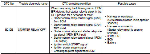
DTC Logic
DTC DETECTION LOGIC
NOTE:• If DTC B210E is displayed with DTC U1000, first perform the trouble diagnosis for DTC U1000. Refer to PCS-59, "DTC Logic". • If DTC B210E is displayed with DTC B209F, first perform the trouble diagnosis for DTC B209F. Refer to SEC-209, "DTC Logic". • If DTC B210E is displayed with DTC B20A0, first perform the trouble diagnosis for DTC B20A0. Refer to SEC-211, "DTC Logic".
• When IPDM E/R power supply voltage is low (Approx. 7 - 8 V for about 1 second), the DTC B210E may be detected.
DTC CONFIRMATION PROCEDURE
1.PERFORM DTC CONFIRMATION PROCEDURE 1. Press push-button ignition switch under the following conditions to start engine, and wait 5 seconds or more.- Selector lever: In the P position - Brake pedal: Depressed 2. Check DTC in “Self Diagnostic Result” mode of “IPDM E/R” using CONSULT-III.
Is DTC detected? YES >> Go to SEC-220, "Diagnosis Procedure".
NO >> GO TO 2.
2.PERFORM DTC CONFIRMATION PROCEDURE 2 1. Stop engine. 2. Perform DTC CONFIRMATION PROCEDURE for DTC P1650. Refer to EC-366, "DTC Logic" (MR16DDT) or EC-725, "DTC Logic" (HR16DE). 3. Turn ignition switch ON.4. Check DTC in “Self Diagnostic Result” mode of “IPDM E/R” using CONSULT-III.
Is DTC detected? YES >> Refer to SEC-220, "Diagnosis Procedure".
NO >> INSPECTION END
Diagnosis Procedure
1.CHECK STARTER RELAY CONTROL SIGNAL 1. Turn ignition switch ON.2. Check voltage between IPDM E/R harness connector and ground.

Is the inspection result normal? YES >> GO TO 4.
NO >> GO TO 2.
2.CHECK CRANKING REQUEST SIGNAL CIRCUIT 1. Turn ignition switch OFF. 2. Disconnect IPDM E/R connector. 3. Disconnect ECM connector.4. Check continuity between IPDM E/R harness connector and ECM harness connector.

5. Check continuity between BCM harness connector and ground.

Is the inspection result normal? YES >> GO TO 3.
NO >> Repair or replace harness.
3.REPLACE ECMReplace ECM.
Refer to EC-447, "Removal and Installation" (MR16DDT) or EC-805, "Removal and Installation" (HR16DE).
>> INSPECTION END
4.CHECK STARTER RELAY POWER SUPPLY 1. Turn ignition switch OFF.2. Check voltage between IPDM E/R harness connector and ground.

Is the inspection result normal? YES >> GO TO 5.
NO >> Repair or replace harness. Refer to STR-12, "CVT : Wiring Diagram".
5.PERFORM DTC CONFIRMATION PROCEDURE AGAIN 1. Turn ignition switch ON. 2. Select “Self Diagnostic Result” mode of “IPDM E/R” using CONSULT-III. 3. Touch “ERASE”.4. Perform DTC CONFIRMATION PROCEDURE for DTC B210D. Refer to SEC-218, "DTC Logic".
Is DTC detected?
YES >> Replace IPDM E/R. Refer to PCS-34, "Removal and Installation".
NO >> INSPECTION END