Exhaust manifold
Exploded View

1. Exhaust manifold cover 2. Harness bracket
3. Air fuel ratio sensor 1 4. Exhaust manifold stay 5. Heat insulator
6. Exhaust manifold
7. Exhaust manifold cover 8. Gasket
 : Engine front
 : Always replace after every
disassembly.
 : N·m (kg-m, in-lb)
 : N·m (kg-m, ft-lb)
Removal and Installation
REMOVAL
1. Remove exhaust front tube. Refer to EX-12, "Exploded View". 2. Remove air duct. Refer to EM-161, "Exploded View". 3. Remove the harness bracket fixing the harness connector of the air-fuel ratio sensor from the cylinder head on the rear right side. 4. Remove exhaust manifold cover.5. Remove the air fuel ratio sensor 1.
• Using heated oxygen sensor wrench [SST: KV10117100] (A), remove air fuel ratio sensor 1.
CAUTION:• If O2 sensor is dropped on to a hard surface like a concrete floor from a height of 0.5 m or more, discard the sensor and use a new one.
• Clean the mounting area of O2 sensor before installing a new O2 sensor.
NOTE:The exhaust manifold can be removed and installed without removing the air fuel ratio sensor 1 (Disassembly of harness connector is necessary).

6. Remove exhaust manifold side mounting bolt of exhaust manifold stay. 7. Remove the harness bracket of air fuel ratio sensor 1 from cylinder head.
8. Remove exhaust manifold.
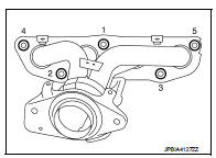
• Loosen nuts in reverse order as shown in the figure.
9. Remove stud bolt from cylinder head.
• Using TORX socket.
10. Remove exhaust manifold cover from exhaust manifold back side.
INSTALLATION
NOte the following, and install in the reverse order of removal.
Exhaust manifold
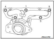
1. Tighten nuts in numerical order as shown in the figure.
2. Tighten to the specified torque again.
Inspection
INSPECTION AFTER REMOVAL
Surface Distortion
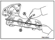
• Using feeler gauge (A) and straightedge (B), check the surface distortion of exhaust manifold mating surface in each exhaust port and entire part.
Limit : Refer to EM-251, "Exhaust Manifold".
• If it exceeds the limit, replace exhaust manifold.