How to set SRT code
Description
OUTLINE
In order to set all SRTs, the self-diagnoses as in the “SRT ITEM” table must have been performed at least once. Each diagnosis may require actual driving for a long period of time under various conditions.
SRT ITEM
The table below shows required self-diagnostic items to set the SRT to “CMPLT”.
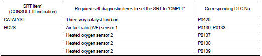
*: Though displayed on the CONSULT-III screen, “HO2S HTR” is not SRT item.
SRT SERVICE PROCEDURE
If a vehicle has failed the state emissions inspection due to one or more SRT items indicating “INCMP”, review the flowchart diagnostic sequence, referring to the following flowchart.
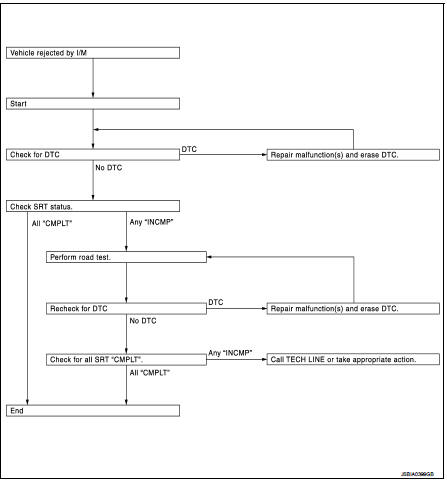
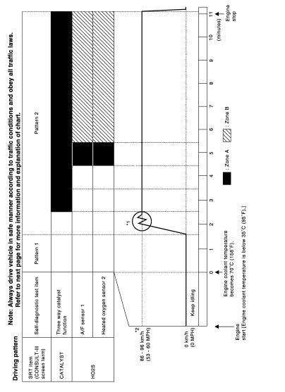
SRT Set Driving Pattern
CAUTION:Always drive the vehicle in safe manner according to traffic conditions and obey all traffic laws.
NOTE:
*1: Depress the accelerator pedal until vehicle speed is 90 km/h, then release the accelerator pedaland keep it released for more than 10 seconds. Depress the accelerator pedal until vehicle speed is 90 km/h again. *2: Checking the vehicle speed with GST is advised.
• The time required for each diagnosis varies with road surface conditions, weather, altitude, individual driving habits, etc.
Zone A refers to the range where the time, required for the diagnosis under normal conditions*, is the shortest.
Zone B refers to the range where the diagnosis can still be performed if the diagnosis is not completed within zone A.
*: Normal conditions refer to the following: • Sea level
• Flat road
• Ambient air temperature: 20 - 30 °C • Diagnosis is performed as quickly as possible under normal conditions.
Under different conditions [For example: ambient air temperature other than 20 - 30 °C], diagnosis may also be performed.
Work Procedure
1.CHECK DTCCheck DTC.
Is any DTC detected? YES >> Repair malfunction(s) and erase DTC. Refer to EC-522, "DTC Index".
NO >> GO TO 2.
2.CHECK SRT STATUS WITH CONSULT-III
Select “SRT STATUS” in “DTC & SRT CONFIRMATION” mode of “ENGINE” using CONSULT-III.
 WITHOUT CONSULT-III
Perform “SRT status” mode with EC-497, "On Board Diagnosis Function".
 WITH GST
Select Service $01 with GST.
Is SRT code(s) set? YES >> END NO-1 >> With CONSULT-III: GO TO 3.
NO-2 >> Without CONSULT-III: GO TO 4.
3.DTC CONFIRMATION PROCEDURE 1. Select “SRT WORK SUPPORT” in “DTC & SRT CONFIRMATION” mode of “ENGINE” using CONSULTIII. 2. For SRT(s) that is not set, perform the corresponding “DTC CONFIRMATION PROCEDURE” according to the “Performance Priority” in the “SRT ITEM” table. Refer to EC-496, "DIAGNOSIS DESCRIPTION : System Readiness Test (SRT) Code".3. Check DTC.
Is any DTC detected? YES >> Repair malfunction(s) and erase DTC. Refer to EC-522, "DTC Index".
NO >> GO TO 7.
4.PERFORM ROAD TEST • Check the “Performance Priority” in the “SRT ITEM” table. Refer to EC-496, "DIAGNOSIS DESCRIPTION : System Readiness Test (SRT) Code".• Perform the most efficient SRT set driving pattern to set the SRT properly. Refer to EC-554, "SRT Set Driving Pattern".
In order to set all SRTs, the SRT set driving pattern must be performed at least once.
>> GO TO 5.
5.PATTERN 1 1. Check the vehicle condition; - Engine coolant temperature is −10 to 35 °C.- Fuel tank temperature is more than 0 °C.
2. Start the engine.3. Keep engine idling until the engine coolant temperature is greater than 70 °C
NOTE:
ECM terminal voltage is follows; • Engine coolant temperature - −10 to 35 °C: 3.0 - 4.3 V - 70°(158°F): Less than 1.4 V
• Fuel tank temperature: Less than 4.1 V Refer to EC-508, "Reference Value".
>> GO TO 6.
6.PATTERN 2 1. Drive the vehicle. And depress the accelerator pedal until vehicle speed is 90 km/h, then release the accelerator pedal and keep it released for more than 10 seconds. 2. Depress the accelerator pedal until vehicle speed is 90 km/h again NOTE:• Checking the vehicle speed with GST is advised.
• When steady-state driving is performed again even after it is interrupted, each diagnosis can be conducted.
In this case, the time required for diagnosis may be extended.
>> GO TO 7.
7.CHECK SRT STATUS WITH CONSULT-III
Select “SRT STATUS” in “DTC & SRT CONFIRMATION” mode of “ENGINE” using CONSULT-III.
 WITHOUT CONSULT-III
Perform “SRT status” mode with EC-497, "On Board Diagnosis Function".
 WITH GST
Select Service $01 with GST.
Is SRT(s) set? YES >> END
NO >> Call TECH LINE or take appropriate action.