Power supply and ground circuit
3. Check the voltage between 4WD control module harness connector and ground.
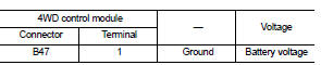
4. Turn the ignition switch ON.
CAUTION:Never start the engine.
5. Check the voltage between 4WD control module harness connector and ground.

Is the inspection result normal? YES >> GO TO 3.
NO >> GO TO 2.
2.CHECK 4WD CONTROL MODULE POWER SUPPLY (2) 1. Turn the ignition switch OFF. 2. Check the 10A fuse (#33).3. Check the harness for open or short between 4WD control module harness connector No.1 terminal and 10A (#33).
Is the inspection result normal? YES >> Perform the trouble diagnosis for power supply circuit. Refer to PG-10, "Wiring Diagram - BATTERY POWER SUPPLY -".
NO >> Repair or replace error-detected parts.
3.CHECK 4WD CONTROL MODULE POWER SUPPLY (3) 1. Turn the ignition switch OFF.2. Check the voltage between 4WD control module harness connector and ground.

3. Turn the ignition switch ON.
CAUTION:Never start the engine.
4. Check the voltage between 4WD control module harness connector and ground.

Is the inspection result normal? YES >> GO TO 5.
NO >> GO TO 4.
4.CHECK 4WD CONTROL MODULE POWER SUPPLY (4) 1. Turn the ignition switch OFF. 2. Check the 10A fuse (#3).3. Check the harness for open or short between 4WD control module harness connector No.3 terminal and 10A (#3).
Is the inspection result normal? YES >> Perform the trouble diagnosis for ignition power supply circuit. Refer to PG-15, "Wiring Diagram - IGNITION POWER SUPPLY -".
NO >> Repair or replace error-detected parts.
5.CHECK 4WD SOLENOID POWER SUPPLY (1) 1. Turn the ignition switch OFF. 2. Disconnect 4WD control module harness connector.3. Check the voltage between 4WD control module harness connector and ground.

4. Turn the ignition switch OFF to ON.
CAUTION:Never start the engine.
5. Check the voltage between 4WD control module harness connector and ground.

Is the inspection result normal? YES >> GO TO 7.
NO >> GO TO 6.
6.CHECK 4WD SOLENOID POWER SUPPLY (2) 1. Turn the ignition switch OFF. 2. Check the 10A fuse (#12).3. Check the harness for open or short between 4WD control module harness connector No.12 and the 10A fuse (#12).
Is the inspection result normal? YES >> Perform the trouble the diagnosis for power supply circuit. Refer to PG-10, "Wiring Diagram - BATTERY POWER SUPPLY -".
NO >> Repair or replace error-detected parts.
7.CHECK 4WD CONTROL MODULE GROUND 1. Turn the ignition switch OFF.2. Check the continuity between 4WD control module harness connector and ground.
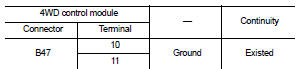
Is the inspection result normal? YES >> INSPECTION END
NO >> Repair or replace error-detected parts.