Transaxle & transmission CVT: RE0F10B

Structure and operation

In this manual: Transaxle & transmission CVT: RE0F10B
Foreword — 1General information — 45Engine Mechanical MR16DDT — 61Engine Mechanical HR16DE — 52Engine Mechanical K9K — 46Engine Lubrication System MR16DDT — 18Engine Lubrication System HR16DE — 14Engine Lubrication System K9K — 11Engine Cooling System MR16DDT — 28Engine Cooling System HR16DE — 29Engine Cooling System K9K — 24Engine Control System MR16DDT — 163Engine Control System HR16DE — 115Engine Control System K9K — 129Fuel System MR16DDT — 13Fuel system HR16DE — 11Fuel system K9K — 12Exhaust system MR16DDT — 7Exhaust system HR16DE — 10Exhaust system K9K — 7Starting system — 24Accelerator control system — 6Clutch — 25Driveline transfer: TY21B — 77Driveline rear propeller Shaft: 3Fφ16-ETJ75 — 12Driveline rear final drive: RTVS — 31Transaxle & transmission 5MT: RS5F92R — 31Transaxle & transmission 6MT: RS6F94R — 30Transaxle & transmission CVT: RE0F10B — 93Transaxle & transmissioN CVT: RE0F11A — 103Front Axle MR16DDT — 18Front Axle HR16DE — 17Front Axle K9K — 17Rear Axle 2WD — 6Rear Axle 4WD — 13Front Suspension — 21Rear Suspension 2WD — 13Rear Suspension 4WD — 17Road Wheels & Tires — 6Brake System LHD — 24Brake System RHD — 24Parking Brake System — 8Brake Control System without ESP — 44Brake Control System with ESP — 63Steering System — 14Steering Control System — 27Seat Belt — 8SRS Airbag — 24SRS Airbag Control System — 93Ventilation System — 11Heater & Air Conditioning System HR16DE — 28Heater & Air Conditioning System MR16DDT — 28Heater & Air Conditioning Control System Type 1 — 49Heater & Air Conditioning Control System Type 2 — 51Heater & Air Conditioning Control System Type 3 — 32Heater & Air Conditioning Control System Type 4 — 40Heater & Air Conditioning Control System Type 5 — 21Interior — 16Instrument Panel — 10Seat — 18Door & Lock Type 1 — 83Door & Lock type 2 — 80Door & Lock type 3 — 65Door & Lock type 4 — 60Security Control System with intelligent key system — 82Security Control System without intelligent key system — 41Glass & Window System — 15Power Window Control System — 28Body Repair — 13Exterior — 20Mirrors — 26Exterior Lighting System Halogen type — 51Interior Lighting System — 24Wiper & Washer — 45Defogger — 31Horn — 4Power Outlet — 4Body Control System With intelligent key system — 21Body Control System Without intelligent key system — 23LAN system can fundamental — 6LAN system can — 31LAN System can system (type 1) — 1LAN System can system (type 2) — 1LAN System can system (type 3) — 1LAN System can system (type 4) — 1LAN System can system (type 5) — 1LAN System can system (type 6) — 1LAN System can system (type 7) — 2LAN System can system (type 8) — 1LAN System can system (type 9) — 1LAN System can system (type 10) — 1LAN System can system (type 11) — 1Power Control System IPDM E/R (with I-key) — 14Power Control System IPDM E/R (without I-key) — 14Power Control System Power distribution system — 25Charging System — 22Power Supply, Ground & Circuit Elements — 20Meter, Warning Lamp & Indicator — 33Warning Chime System — 22Audio, Visual & Navigation System Audio without navigation — 30Audio, Visual & Navigation System Audio with navigation — 33Audio, Visual & Navigation System NISSAN dynamic control system — 22Cruise Control System — 1Drive Mode System — 10Maintenance — 14
~3min read

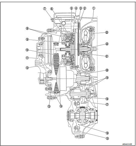
Transaxle : Cross-Sectional View

1. Converter housing

1. Converter housing 2. Driven sprocket
3. Chain
4. Reverse brake
5. Oil pump
6. Forward clutch
7. Planetary carrier
8. Primary pulley
9. Sun gear
10. Steel belt
11. Side cover
12. Internal gear
13. Parking gear
14. Secondary pulley
15. Final gear
16. Differential case
17. Idler gear
18. Reduction gear
19. Taper roller bearing 20. Output gear
21. Drive sprocket
22. Input shaft
23. Torque converter

Transaxle : Operation Status
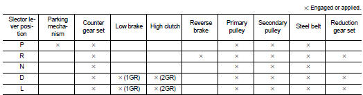
Transaxle : Transaxle Mechanism

Transaxle : Transaxle Mechanism

BELT & PULLEY

Mechanism
It is composed of a pair of pulleys (the groove width is changed freely in the axial direction) and the steel belt (the steel plates are placed continuously and the belt is guided with the multilayer steel rings on both sides).

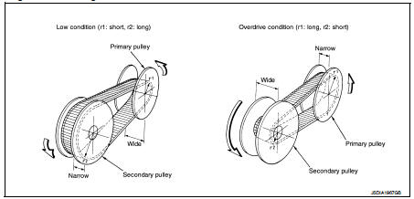
The groove width changes according to wrapping radius of steel belt and pulley from low status to overdrive status continuously with non-step. It is controlled with the oil pressures of primary pulley and secondary pulley.

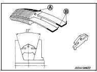
Steel belt
It is composed of multiple steel plates (A) and two steel rings (B) stacked to a several number. The feature of this steel belt transmits power with compression of the steel plate in contrast with transmission of power in pulling with a rubber belt. Friction force is required with the pulley slope to transmit power from the steel plate. The force is generated with the following mechanism: Oil pressure applies to the secondary pulley to nip the plate. ⇒The plate is pushed and extended outward. ⇒The steel ring shows withstands.

⇒Pulling force is generated on the steel ring. ⇒The plate of the primary pulley is nipped between the pulley. ⇒Friction force is generated between the steel belt and the pulley.

Therefore, responsibilities are divided by the steel plate that transmits the power with compression and the steel ring that maintains necessary friction force. In this way, the tension of the steel ring is distributed on the entire surface and stress variation is limited, resulting in good durability.
Pulley

Pulley
The primary pulley (input shaft side) and the secondary pulley (output shaft side) have the shaft with slope (fixed cone surface), movable sheave (movable cone surface that can move in the axial direction) and oil pressure chamber at the back of the movable sheave.
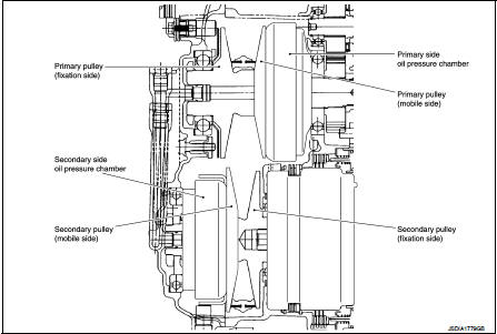
Pulley gear shifting operation

Pulley gear shifting operation • Pulley gear shifting operation The movable sheave slides on the shaft to change the groove width of the pulley. Input signals of engine load (accelerator pedal opening), engine revolution and gear ratio (vehicle speed) change the operation pressures of the primary pulley and the secondary pulley, and controls the pulley groove width. Along with change of the pulley groove width, the belt contact radius is changed. This allows continuous and stepless gear shifting from low to overdrive. “The contact radius ratio of each pulley in contact with the belt x auxiliary gearbox gear ratio” is the gear ratio.
AUXILIARY GEARBOX MECHANISM

AUXILIARY GEARBOX MECHANISM

1st, 2nd and reverse gears are changed with the planetary gear mechanism.

Transaxle : Oil Pressure System

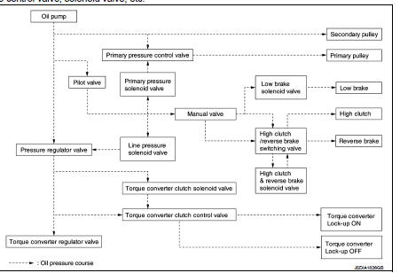
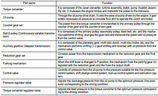
Oil pressure required for operation of the transaxle transmission mechanism is generated by oil pump, oil pressure control valve, solenoid valve, etc.
Transaxle : Component Description
Transaxle : Component Description


System