B130b Rear Right Speaker
DTC DETECTION LOGIC
| DTC No. | CONSULT screen terms (Trouble diagnosis content) | DTC detection condition | ||
|---|---|---|---|---|
| B130B–13 | Rear RH speaker (Rear door speaker RH) |
[OPEN] | Diagnosis condition | When ignition switch is ON. |
| Signal (terminal) |
|
|||
| Threshold | – | |||
| Diagnosis delay time | 30 seconds or more | |||
| B130B–1C | [SHORT] | Diagnosis condition | When ignition switch is ON. | |
| Signal (terminal) |
|
|||
| Threshold | – | |||
| Diagnosis delay time | 30 seconds or more | |||
| B130B–11 | [GND–SHORT] | Diagnosis condition | When ignition switch is ON. | |
| Signal (terminal) |
|
|||
| Threshold | – | |||
| Diagnosis delay time | 30 seconds or more | |||
| B130B–12 | [VB–SHOR] | Diagnosis condition | When ignition switch is ON. | |
| Signal (terminal) |
|
|||
| Threshold | – | |||
| Diagnosis delay time | 30 seconds or more | |||
POSSIBLE CAUSE
RR SP RH+ open, short, short to ground, short to voltage
RR SP RH− open, short, short to ground, short to voltage
Rear door speaker RH
AV control unit
FAIL-SAFE
Rear door speaker RH inoperative.
PERFORM DTC CONFIRMATION PROCEDURE
 CONSULT
Ignition switch ON.
Ignition switch OFF and wait at least 30 seconds.
Ignition switch ON and wait at least 30 seconds or more.
Select “Self Diagnostic Result” mode of “MULTI AV”.
Check DTC.
Is DTC B130B detected?
YES>>Proceed to DTC Diagnosis Procedure.
NO>>To check malfunction symptom before repair: Refer to Intermittent Incident.
NO>>Confirmation after repair: Inspection End.
DETERMINE MALFUNCTION TYPE
CONSULT
Ignition switch ON.
Ignition switch OFF and wait at least 30 seconds.
Ignition switch ON and wait at least 30 seconds or more.
Select “Self Diagnostic Result” mode of “MULTI AV”.
Check DTC.
Is DTC B130B–11, 12, 13 or 1C detected?
YES>>13 [OPEN], or 11 [GND–SHORT] – GO TO 2.
YES>>1C [SHORT] – GO TO 3.
YES>>12 [VB–SHOR] – GO TO 4.
NO>>Refer to Intermittent Incident.
CHECK SOUND SIGNAL CIRCUITS FOR OPEN OR SHORT TO GROUND
Ignition switch OFF.
Disconnect AV control unit connector and rear door speaker RH connector.
Check the continuity between AV control unit connector and rear door speaker RH connector.
AV control unit Rear door speaker RH Continuity Connector Terminal Connector Terminal M161 13 D306 1 Yes 14 2 Check the continuity between AV control unit connector and ground.
AV control unit Continuity Connector Terminal Ground M161 13 — No 14
Is the inspection result normal?
YES>>GO TO 5.
NO>>Repair or replace harness or connectors.
CHECK SOUND SIGNAL CIRCUITS FOR SHORT
Ignition switch OFF.
Disconnect AV control unit connector and rear door speaker RH connector.
Check the continuity between the terminals of AV control unit connector.
AV control unit Continuity Connector Terminal M161 13 14 No
Is the inspection result normal?
YES>>GO TO 5.
NO>>Repair or replace harness or connectors.
CHECK SOUND SIGNAL CIRCUIT FOR SHORT TO POWER SUPPLY
Ignition switch OFF.
Disconnect AV control unit connector and rear door speaker RH connector.
Ignition switch ON.
Check the voltage between AV control unit connector and ground.
AV control unit Ground Voltage
(Approx.)Connector Terminal M161 13 — 0 V 14
Is the inspection result normal?
YES>>GO TO 5.
NO>>Repair or replace harness or connectors.
CHECK REAR RH SPEAKER SIGNAL
Connect AV control unit connector and rear door speaker RH connector.
Ignition switch ON.
Push AV control unit POWER switch.
Check signal between the terminals of AV control unit connector.
AV control unit Condition Reference value Connector (+) (−) Terminal Terminal M161 13 14 Audio signal output 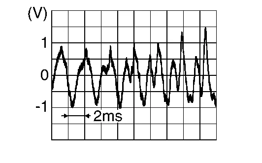
Is the inspection result normal?
YES>>Replace rear door speaker RH. Refer to Removal and Installation.
NO>>Replace AV control unit. Refer to Removal and Installation.