Preliminaries
1. APPLICABILITY OF THIS DOCUMENT
This document describes the diagnosis applicable to all Electronic Control Units with the following characteristics:
| Vehicle(s): MEGANE II Function concerned: Xenon lamps |
ECU name: Discharge lamp Program no.: VDIAG no.: 04 |
2. ESSENTIAL ITEMS FOR DIAGNOSIS
Documentation type
Diagnostic methods (this document):
- Assisted diagnosis (built into the diagnostic tool), paper (Repair Manual or Technical Note), Dialogys.
Wiring diagrams:
- Visu-Schéma (CD-ROM), paper.
Diagnostic tool type
- CLIP
Essential tool type
ESSENTIAL SPECIALIST TOOLS |
| Multimeter |
3. REMINDERS
Fault diagnosis:
There are faults declared as present and faults declared as stored, which appeared under certain conditions and have since disappeared, or which are still present but were not diagnosed under the current conditions.
The "current" or "stored" fault status must be checked when starting the diagnostic tool after switching on ignition (without operating any components of the system).
For a present fault, deal with the fault following the procedure given in the chapter "Fault interpretation".
For a stored fault, note the displayed faults and follow the instructions in the "Instructions" section.
If the fault is confirmed by the instructions section, the fault is present again. In this case, rectify the fault.
If the fault is not confirmed, carry out the basic checks. To do so, check:
- the electrical circuits corresponding to the fault,
- the connectors of these lines (corrosion, bent pins, etc.),
- the resistance of the component detected as faulty,
- the condition of the wiring (melted or cut insulation, chafing).
Conformity check
The conformity check aims to verify the states and parameters that show no fault on the diagnostic tool when they are inconsistent. This step therefore allows you to:
- diagnosing faults with no fault code displayed that may correspond to a customer complaint.
- verify correct operation of the system and make sure a fault will not reappear after repair.
This chapter therefore contains a diagnosis of states and parameters, under the conditions required for their check.
If a state does not operate normally or a parameter is out of tolerance, refer to the corresponding diagnostic page.
Customer symptoms - Fault location tree
If the diagnostic tool check is correct but the customer complaint is still present, deal with the problem using "customer complaints".
A summary of the overall procedure is shown as a flowchart on the next page.4. DIAGNOSTIC PROCEDURE
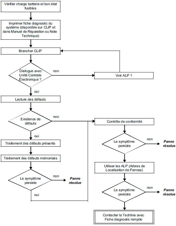
5. DIAGNOSTIC SHEET
WARNING: All incidents on a complex system must be subject to a full diagnosis using suitable tools. The DIAGNOSIS SHEET, to be completed during the diagnosis, keeps a record of the diagnosis performed. It forms part of the dialogue with the manufacturer.
A DIAGNOSTIC SHEET MUST BE COMPLETED EVERY TIME A DIAGNOSIS IS PERFORMED.This sheet will always be required:
- when requesting technical assistance from the Techline.
- for approval requests, when replacing parts for which approval is mandatory.
- to attach it to the "under observation" parts requested on return. It then conditions the warranty refund and contributes to a better analysis of the removed parts.
6 - SAFETY INSTRUCTIONS
Any work on a component requires compliance with safety rules to avoid any material damage or personal injury:
- Check that the battery is correctly charged to avoid damage to the ECUs in case of low charge.
- Use the appropriate tools.
- Do not touch the Xenon lamps with your hands.
- Do not work on the COSLAD system while it is powered; the voltage is greater than or equal to 20,000 V.
PRELIMINARY DIAGNOSIS
NOTES
1 - ARCHITECTURE OF THE "HEADLAMP LEVELLING FOR DISCHARGE LAMPS" FUNCTION:
The system consists of the following independent components:
- front height sensor,
- rear height sensor,
- two levelling units (front right and front left) comprising (in the headlamp):
- Xenon lamp,
- high-voltage power unit,
- ECU
2 - SYSTEM OPERATION
The user operates the control stalk (dipped beam); the stalk sends a signal to the Cabin Central Unit. The Cabin Central Unit processes this signal and requests the protection and switching unit via the CAN network to control the power supply of the Xenon lamp control modules.
These modules supply the high-voltage power units; the bulbs light up.
Note: When the lights are switched on, the headlamp moves to three positions (low, high, initial) for levelling according to speed, then moves to its nominal position according to the vehicle attitude.System diagnosis
Three separate topics appear in the "discharge lamps" area:
- Right lamp.
- Left lamp.
- Lamp: specific to replacing a control module in the aftermarket.
The conditions required to diagnose the system are:
- vehicle on charge (RENAULT approved tool),
- dipped beams switched on (power supply to the Xenon lamp systems).
3 - SYSTEM CONFIGURATION - CALIBRATION
To be carried out when replacing a component of the system (example: sensor, headlamp...).
To ensure correct "configuration-calibration", follow the procedure below:
- Carry out a mechanical adjustment of the headlamps.
Place the vehicle on a level surface in normal operating conditions (empty boot), and the sensor control linkage must not be damaged.
- Vehicle stationary, with no change in attitude (no door slamming).
- Driver on board.
- Full fuel tank.
- Lights on.
Module address (CF004): after replacing a levelling unit or a module, carry out the following procedure:
- enter the system diagnosis via the "discharge lamps" area, topic "lad" (lights on),
- assign the new module address according to its position on the vehicle (right or left),
- exit diagnostic mode,
- switch off the dipped beams, wait a few seconds,
- switch the lights on and re-enter diagnostic mode via the "discharge lamps" area,
- carry out the configurations and calibrations described below.
Vehicle type (CF003)
This configuration activates the correction laws suited to the body type and equipment level of the vehicle.
The new laws will take effect after switching the dipped beams off and on again.
To carry out the configuration, proceed as follows:
- enter diagnostic mode for the "discharge lamps" area,
- carry out configuration CF003 according to the body type:
- B-C 84
- L-K 84
- E 84
- exit diagnostic mode,
- switch the dipped beams off and on again,
- check that the initial front and rear positions are between 30% < X < 70%.
Module calibration (CF001):
This configuration stores the vehicle reference attitude (application condition) and sets the headlamps to nominal position.
To carry out the configuration, proceed as follows:
- enter diagnostic mode for the "discharge lamps" area,
- carry out configuration CF001.
Initial sensor position 30% < X < 70% (parameters PR004 and PR005).
- exit diagnostic mode,
- switch the lights off and on again.
This operation must be carried out whenever work is done on the body height sensors.
NOTE: When replacing the module, also enter the vehicle VIN (VP004).
4 - DEGRADED MODE MANAGEMENT
Following a fault on the discharge lamp system, the module turns on the service warning light.
Degraded mode 1: the actuators move slowly to a defined positionDegraded mode 2: no correction according to acceleration and braking
Degraded mode 3: no correction according to load
5 - CONNECTION
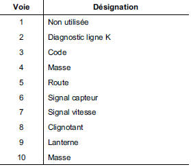
Headlamp connector, 10-way
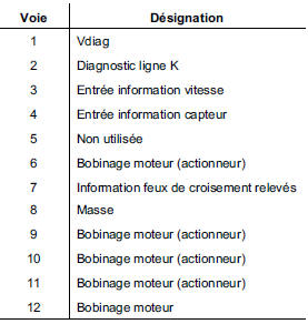
Ballast connector, 12-way
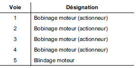
Actuator connector, 5-way
Test yourself
A quick Renault Megane quiz: every answer comes with an explanation and a link to the manual page.