Downhill Assist Control Switch
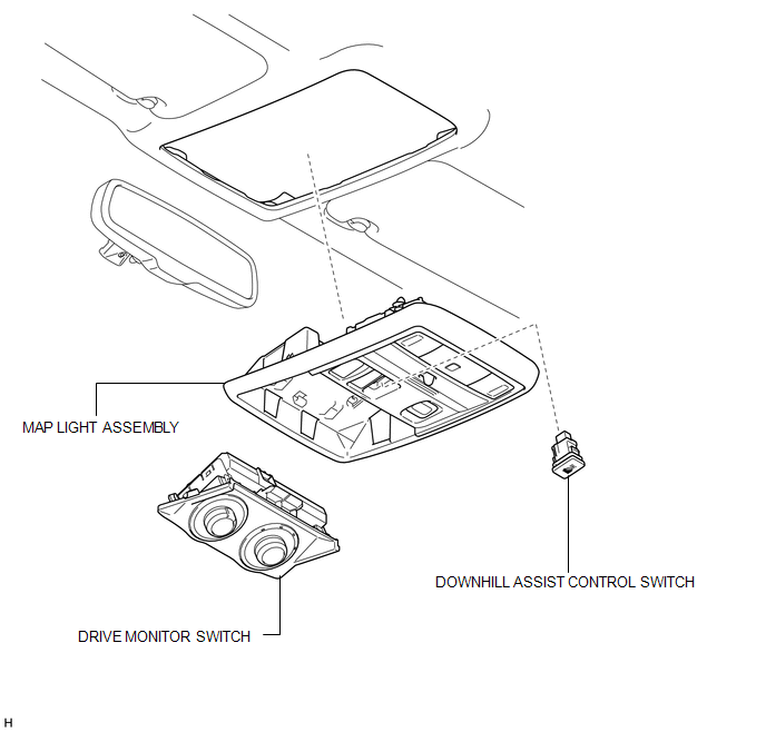
Removal REMOVAL PROCEDURE
1. REMOVE DRIVE MONITOR SWITCH

2. REMOVE MAP LIGHT ASSEMBLY
3. REMOVE DOWNHILL ASSIST CONTROL SWITCH
(a) Disconnect the 2 connectors. |
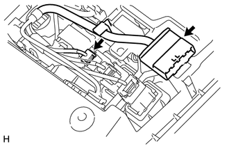 |
(b) Using a screwdriver, detach the 2 claws and remove the downhill assist control switch from the map light assembly. HINT: Tape the screwdriver tip before use. |
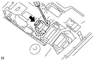 |
1. CHECK DOWNHILL ASSIST CONTROL SWITCH
(a) Measure the resistance according to the value(s) in the table below. Standard Resistance:
If the result is not as specified, replace the downhill assist control switch. |
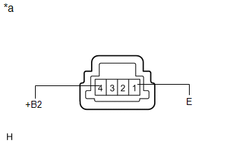 |
1. INSTALL DOWNHILL ASSIST CONTROL SWITCH
(a) Attach the 2 claws to install the downhill assist control switch to the map lamp assembly. |
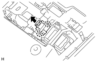 |
(b) Connect the 2 connectors.
2. INSTALL MAP LIGHT ASSEMBLY

3. INSTALL DRIVE MONITOR SWITCH
4. PERFORM DOWNHILL ASSIST CONTROL CALIBRATION
(a) Perform downhill assist control switch calibration (See page ).
Test yourself
A quick Toyota 4Runner quiz: every answer comes with an explanation and a link to the manual page.