Hazard Warning Switch
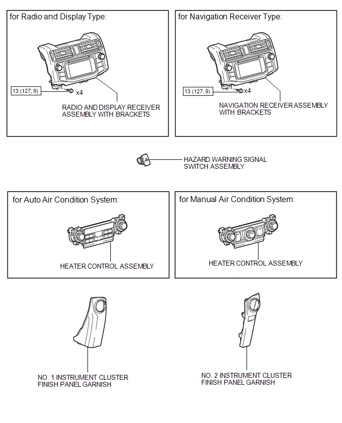
Removal REMOVAL PROCEDURE
1. REMOVE NO. 1 INSTRUMENT CLUSTER FINISH PANEL GARNISH

2. REMOVE NO. 2 INSTRUMENT CLUSTER FINISH PANEL GARNISH
3. REMOVE HEATER CONTROL ASSEMBLY
4. REMOVE RADIO AND DISPLAY RECEIVER ASSEMBLY WITH BRACKETS (for Radio and Display Type)
5. REMOVE NAVIGATION RECEIVER ASSEMBLY WITH BRACKETS (for Navigation Receiver Type)
6. REMOVE HAZARD WARNING SIGNAL SWITCH ASSEMBLY
(a) Disconnect the connector. |
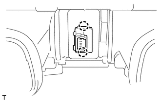 |
(b) Detach the 2 claws to remove the hazard warning signal switch assembly.
Inspection INSPECTION PROCEDURE1. INSPECT HAZARD WARNING SIGNAL SWITCH ASSEMBLY
(a) Measure the resistance according to the value(s) in the table below. Standard Resistance:
|
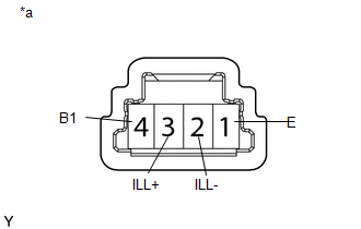 |
(b) Apply battery voltage to the connector and check the LED illumination condition.
OK:
Measurement Condition | Specified Condition |
|---|---|
Battery positive (+) → Terminal 3 (ILL+) Battery negative (-) → Terminal 2 (ILL-) |
LED illuminates |
If the result is not as specified, there may be a malfunction in the hazard warning signal switch.
Text in Illustration*a |
Component without harness connected (Hazard Warning Signal Switch Assembly) |
1. INSTALL HAZARD WARNING SIGNAL SWITCH ASSEMBLY
(a) Attach the 2 claws to install the hazard warning signal switch assembly.
(b) Connect the connector.
2. INSTALL RADIO AND DISPLAY RECEIVER ASSEMBLY WITH BRACKETS (for Radio and Display Type)

3. INSTALL NAVIGATION RECEIVER ASSEMBLY WITH BRACKETS (for Navigation Receiver Type)
4. INSTALL HEATER CONTROL ASSEMBLY
5. INSTALL NO. 1 INSTRUMENT CLUSTER FINISH PANEL GARNISH
6. INSTALL NO. 2 INSTRUMENT CLUSTER FINISH PANEL GARNISH
Test yourself
A quick Toyota 4Runner quiz: every answer comes with an explanation and a link to the manual page.