Stop Light Switch
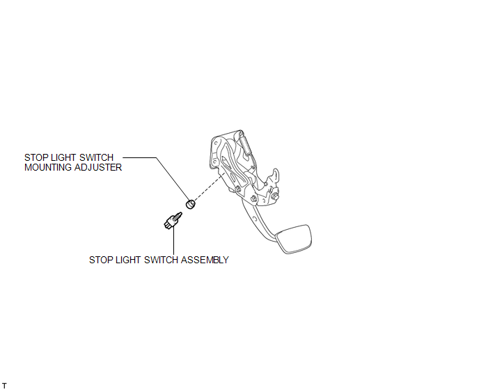
On-vehicle Inspection ON-VEHICLE INSPECTION PROCEDURE
1. INSPECT STOP LIGHT SWITCH ASSEMBLY
(a) Disconnect the connector from the stop light switch assembly. |
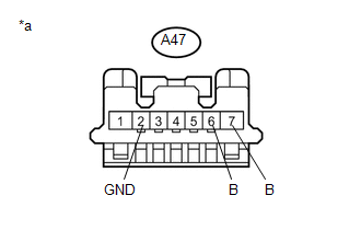 |
(b) Measure the voltage according to the value (s) in the table below.
Standard Voltage:
Tester Connection | Condition | Specified Condition |
|---|---|---|
A47-7 (B) - A47-2 (GND) |
Ignition switch off |
11 to 14 V |
A47-6 (B) - A47-2 (GND) |
Ignition switch ON |
11 to 14 V |
*a |
Front view of wire harness connector (to Stop Light Switch Assembly) |
(c) Measure the resistance according to the value(s) in the table below.
Standard Resistance:
Tester Connection | Condition | Specified Condition |
|---|---|---|
A47-2 (GND) - Body ground |
Always |
Below 1 Ω |
(d) Reconnect the connector to the stop light switch assembly. |
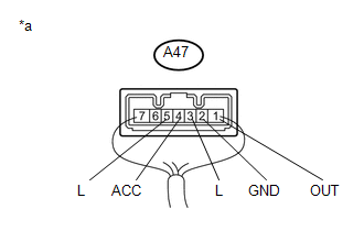 |
(e) Measure the voltage according to the value (s) in the table below.
Standard Voltage:
Tester Connection | Condition | Specified Condition |
|---|---|---|
A47-1 (OUT) - A47-2 (GND) |
Ignition switch off, brake pedal not depressed |
Below 1 V |
A47-1 (OUT) - A47-2 (GND) |
Ignition switch off, brake pedal depressed |
11 to 14 V |
A47-3 (L) - A47-2 (GND) |
Ignition switch off, brake pedal not depressed |
Below 1 V |
A47-4 (ACC) - A47-2 (GND) |
Ignition switch off |
11 to 14 V |
A47-3 (L) - A47-2 (GND) |
Ignition switch off, brake pedal depressed |
11 to 14 V |
A47-5 (L) - A47-2 (GND) |
Ignition switch ON, brake pedal not depressed |
11 to 14 V |
A47-5 (L) - A47-2 (GND) |
Ignition switch ON, brake pedal depressed |
Below 1 V |
*a |
Component with harness connected (Stop Light Switch Assembly) |
If the result is not as specified, replace the stop light switch assembly.
Removal REMOVAL PROCEDURE1. REMOVE STOP LIGHT SWITCH ASSEMBLY
(a) Disconnect the connector. |
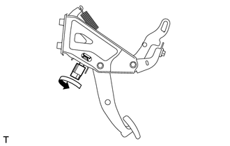 |
(b) Turn the stop light switch counterclockwise and remove the stop light switch.
2. REMOVE STOP LIGHT SWITCH MOUNTING ADJUSTER
(a) Remove the stop light switch mounting adjuster.
Installation INSTALLATION PROCEDURE1. INSTALL STOP LIGHT SWITCH MOUNTING ADJUSTER
(a) Install the stop light switch mounting adjuster to the pedal support.
2. INSTALL STOP LIGHT SWITCH ASSEMBLY
(a) Install the stop light switch to the adjuster so that the switch body slightly touches the brake pedal. Text in Illustration
NOTICE: Do not depress the brake pedal. |
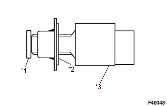 |
(b) Rotate the stop light switch counterclockwise so that the clearance is between 1.5 and 2.5 mm (0.0590 to 0.0984 in.) as shown in the illustration. Torque: 1,5 N·m {15 kgf·cm, 13 in·lbf} Text in Illustration
NOTICE: Do not depress the brake pedal. |
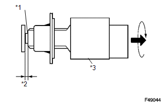 |
(c) Check the stop light switch clearance.
Stop light switch clearance:
1.5 to 2.5 mm (0.0590 to 0.0984 in.)
(d) Connect the connector to the stop light switch.
Test yourself
A quick Toyota 4Runner quiz: every answer comes with an explanation and a link to the manual page.