Installation
1. INSTALL CENTER CONTROL ABSORBER BRACKET LH
(a) Install the center control absorber bracket with the 2 bolts.
Torque:
29 N·m {296 kgf·cm, 21 ft·lbf}
2. INSTALL CENTER CONTROL ABSORBER BRACKET RH
HINT:
Use the same procedure described for the LH side.
3. INSTALL CENTER CONTROL ABSORBER ASSEMBLY LH
(a) Install the center control absorber assembly with the 3 nuts. Torque: 29 N·m {296 kgf·cm, 21 ft·lbf} |
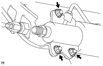 |
(b) Connect the tube to the 2 clamps. |
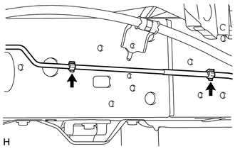 |
(c) Install the bracket with the bolt. Torque: 29 N·m {296 kgf·cm, 21 ft·lbf} |
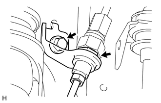 |
(d) While using a wrench to hold the bracket, connect the joint.
Torque:
25 N·m {255 kgf·cm, 18 ft·lbf}
HINT:
For the joint that connects supplied parts, tighten the joint while checking the gap spacing shown in the illustration.
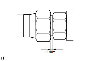
Standard clearance:
1 mm (0.0394 in.)
4. INSTALL CENTER CONTROL ABSORBER ASSEMBLY RH
HINT:
Use the same procedure described for the LH side.
5. INSTALL NO. 1 CENTER CONTROL ABSORBER TUBE LH
(a) Install a new No. 1 center control absorber tube with the bolt. Torque: 29 N·m {296 kgf·cm, 21 ft·lbf} |
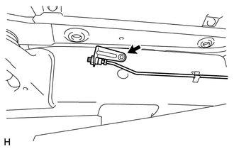 |
(b) While using a wrench to hold the center control absorber assembly, connect the joint.
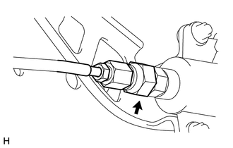
Torque:
25 N·m {255 kgf·cm, 18 ft·lbf}
HINT:
For the joint that connects supplied tubes, tighten the joint while checking the gap spacing shown in the illustration.
Standard clearance:
1 mm (0.0394 in.)
(c) Pass the center control absorber tube between the body and frame.
(d) Attach the 2 clamps. |
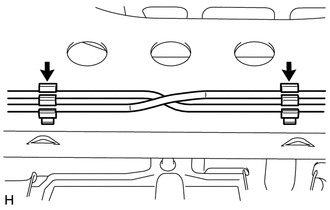 |
(e) While using a wrench to hold the bracket, connect the joint.
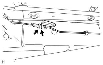
Torque:
25 N·m {255 kgf·cm, 18 ft·lbf}
HINT:
For the joint that connects supplied tubes, tighten the joint while checking the gap spacing shown in the illustration.
Standard clearance:
1 mm (0.0394 in.)
(f) While using a wrench to hold the bracket, connect the joint.
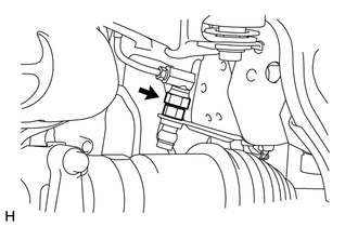
Torque:
25 N·m {255 kgf·cm, 18 ft·lbf}
HINT:
For the joint that connects the supplied tubes, tighten the joint while checking the gap spacing shown in the illustration.
Standard clearance:
1 mm (0.0394 in.)
6. INSTALL NO. 1 CENTER CONTROL ABSORBER TUBE RH
HINT:
Use the same procedure described for the LH side.
7. INSTALL TUBE PROTECTOR LH
(a) Install the tube protector LH with the bolt. Torque: 29 N·m {296 kgf·cm, 21 ft·lbf} |
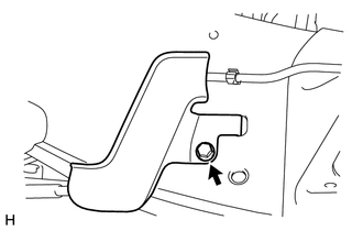 |
8. INSTALL TUBE PROTECTOR RH
HINT:
Use the same procedure described for the LH side.
9. INSTALL FRONT WHEEL

10. INSTALL REAR WHEEL
11. INSPECT FOR FLUID LEAK
Test yourself
A quick Toyota 4Runner quiz: every answer comes with an explanation and a link to the manual page.