Terminals Of Ecu
1. AIR CONDITIONING AMPLIFIER
(a) Measure the voltage and resistance according to the value(s) in the table below.
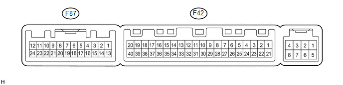
Terminal No. (Symbol) | Wiring Color | Terminal Description | Condition | Specified Condition |
|---|---|---|---|---|
F87-9 (ROUT) - Body ground |
LG - Body ground |
Output climate control signal (Front passenger side) |
Engine switch on (IG) Refreshing seat switch RH blower side level 3 |
Pulse generation (see waveform 1) |
F87-10 (LOUT) - Body ground |
L - Body ground |
Output climate control signal (Driver side) |
Engine switch on (IG) Refreshing seat switch LH blower side level 3 |
Pulse generation (see waveform 1) |
F87-15 (SW 5) - Body ground |
W - Body ground |
Input climate control signal (Front passenger side) |
Engine switch on (IG) Refreshing seat switch RH level 0 |
4.5 to 5.5 V |
Engine switch on (IG) Refreshing seat switch RH blower side level 3 |
Below 1 V |
|||
F87-16 (SW 4) - Body ground |
V - Body ground |
Input climate control signal (Driver side) |
Engine switch on (IG) Refreshing seat switch LH level 0 |
4.5 to 5.5 V |
Engine switch on (IG) Refreshing seat switch LH blower side level 3 |
Below 1 V |
|||
F42-31 (S5-4) - Body ground |
V - Body ground |
Power supply |
Engine switch on (IG) |
4.5 to 5.5 V |
F42-35 (SG-4) - Body ground |
SB - Body ground |
Ground |
Always |
Below 1 Ω |
If the result is not as specified, the air conditioning amplifier may have a malfunction.
(1) Using an oscilloscope, check waveform 1.
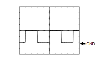 Waveform 1 (Reference)
Item | Content |
|---|---|
Terminal No. (Symbol) |
F87-9 (ROUT) - Body ground F87-10 (LOUT) - Body ground |
Tool Setting |
2 V/DIV., 500 μsec/DIV. |
Condition |
Engine switch on (IG) Refreshing seat switch blower side level 3 |
Test yourself
A quick Toyota 4Runner quiz: every answer comes with an explanation and a link to the manual page.