On-vehicle Inspection
1. INSPECT SEAT HEATER CONTROL SUB-ASSEMBLY LH
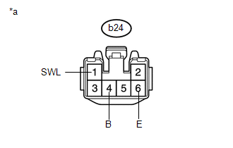
(a) Disconnect the b24 seat heater control sub-assembly LH connector. |
 |
(b) Measure the resistance according to the value(s) in the table below.
Standard Resistance:
Tester Connection | Condition | Specified Condition |
|---|---|---|
b24-6 (E) - Body ground |
Always |
Below 1 Ω |
(c) Measure the voltage according to the value(s) in the table below.
Standard Voltage:
Tester Connection | Switch Condition | Specified Condition |
|---|---|---|
b24-1 (SWL) - b24-6 (E) |
Engine switch on (IG) Refreshing seat switch LH side off |
Below 1 V |
Engine switch on (IG) Refreshing seat switch LH side on |
11 to 14 V |
|
b24-4 (B) - b24-6 (E) |
Engine switch off |
Below 1 V |
Engine switch on (IG) |
11 to 14 V |
*a |
Front view of wire harness connector (to Seat Heater Control Sub-assembly LH) |
If the result is not as specified, there may be a malfunction on the wire harness side.
(d) Connect the b24 seat heater control sub-assembly LH connector.
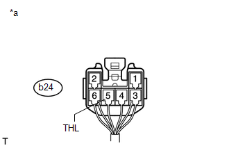
(e) Measure the voltage according to the value(s) in the table below. Standard Voltage:
If the result is not as specified, the seat heater control sub-assembly LH may have a malfunction. |
 |
2. INSPECT SEAT HEATER CONTROL SUB-ASSEMBLY RH
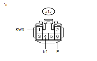
(a) Disconnect the a15 seat heater control sub-assembly LH connector. |
 |
(b) Measure the resistance according to the value(s) in the table below.
Standard Resistance:
Tester Connection | Condition | Specified Condition |
|---|---|---|
a15-6 (E) - Body ground |
Always |
Below 1 Ω |
(c) Measure the voltage according to the value(s) in the table below.
Standard Voltage:
Tester Connection | Switch Condition | Specified Condition |
|---|---|---|
a15-1 (SWR) - a15-6 (E) |
Engine switch on (IG) Refreshing seat switch RH side off |
Below 1 V |
Engine switch on (IG) Refreshing seat switch RH side on |
11 to 14 V |
|
a15-4 (B1) - a15-6 (E) |
Engine switch off |
Below 1 V |
Engine switch on (IG) |
11 to 14 V |
*a |
Front view of wire harness connector (to Seat Heater Control Sub-assembly RH) |
If the result is not as specified, there may be a malfunction on the wire harness side.
(d) Connect the a15 seat heater control sub-assembly LH connector.
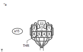
(e) Measure the voltage according to the value(s) in the table below. Standard Voltage:
If the result is not as specified, the seat heater control sub-assembly LH may have a malfunction. |
 |
Test yourself
A quick Toyota 4Runner quiz: every answer comes with an explanation and a link to the manual page.