Removal
REMOVAL
PRECAUTION / NOTICE / HINT
The procedures required (adjustment, calibration, initialization or registration) that must be performed after parts have been removed, installed or replaced during steering gear assembly removal/installation are shown below.
Procedures Required After Replacement / Removal / Installation of PartsReplaced Part or Performed Procedure | Required Procedure | Effect/Inoperative Function When Required Procedure Is Not Performed | Link |
|---|---|---|---|
Front wheel alignment adjustment |
|
|
 |
PROCEDURE
1. ALIGN FRONT WHEELS STRAIGHT AHEAD
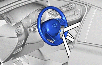
2. SECURE STEERING WHEEL ASSEMBLY
(a) Secure the steering wheel using the seat belt to prevent it from turning. HINT: This precaution is necessary to avoid damaging the clock spring. |
 |
3. REMOVE STEERING COLUMN HOLE COVER SOUND INSULATOR SHEET
Click here
4. DISCONNECT STEERING INTERMEDIATE SHAFT ASSEMBLY NO. 2
Click here
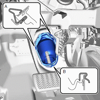
5. DISCONNECT STEERING COLUMN HOLE COVER SUB-ASSEMBLY NO. 1
(a) Disengage the clip (A), release the clamp (B) from the vehicle body, then disconnect the steering column hole cover sub-assembly No. 1. NOTICE: Be careful not to damage the clips (A) or (B). |
 |
6. REMOVE FRONT WHEELS
Click here
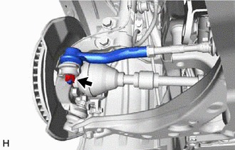
7. DISCONNECT LH TIE ROD END SUB-ASSEMBLY
(a) Remove the cotter pin and nut. |
 |
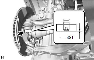
(b) Install the SST on the LH tie rod end sub-assembly. SST: 09960-20010 09961-02060 NOTICE: Make sure the ends of the upper part of the LH steering linkage assembly and the SST are aligned. |
 |
(c) Secure the SST using a rope.
NOTICE:
Pull the rope tight to secure the SST to the LH steering knuckle and prevent the SST from falling.
(d) Using the SST, disconnect the LH tie rod end sub-assembly from the LH steering knuckle.
SST: 09960-20010
09961-02010
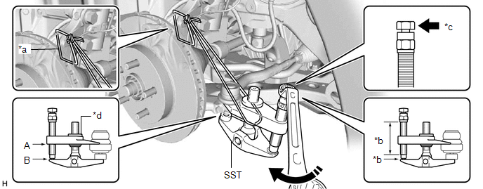
*a |
String |
*b |
Molybdenum disulfide grease application area |
*c |
Place wrench at this location |
*d |
Center nut |
 |
Turn |
- |
- |
CAUTION:
Apply molybdenum grease to the bolt threads and the tip of the SST.
NOTICE:
- Pull the rope tight to secure the SST to the LH steering knuckle and prevent the SST from falling.
- Reinstall the SST with the center nut so that (A) and (B) shown in the illustration are parallel. Otherwise, the ball joint dust cover may be damaged.
- Be sure to place the wrench at the location shown in the illustration.
- Do not damage the front disc brake dust cover.
- Do not damage the ball joint dust cover.
- Do not damage the LH steering knuckle.
8. DISCONNECT RH TIE ROD END SUB-ASSEMBLY
HINT:
Perform the same procedure as for the left side.
9. REMOVE STEERING LINKAGE ASSEMBLY
(a) Disconnect the connector. |
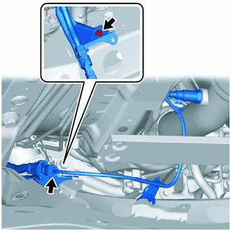 |
(b) Remove the bolt and detach the wire harness clamp bracket from the front suspension member sub-assembly.
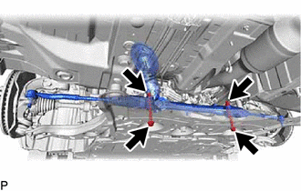
(c) Remove the 2 bolts, 2 nuts and steering linkage assembly from the front suspension member sub-assembly. NOTICE: Do not turn the nut as it has a stopper. Loosen the bolt with the nut in place. |
 |
(d) Remove the steering column hole cover sub-assembly No. 1 from the steering linkage assembly. |
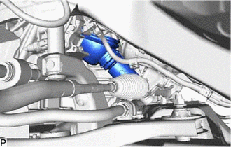 |
(e) Remove the power steering linkage assembly as shown in the illustration.
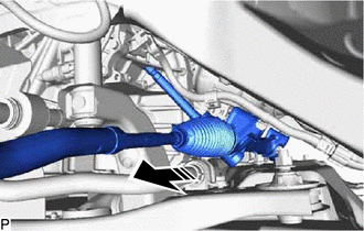
|
Remove in this direction |
10. SECURE STEERING LINKAGE ASSEMBLY
(a) Using the SST, secure the steering linkage assembly in a vise. SST: 09612-00012 HINT: Wrap the SST with protective tape before using it. |
|
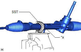
11. REMOVE LH TIE ROD END SUB-ASSEMBLY
(a) Place alignment marks on the LH tie rod end sub-assembly and the steering gear assembly. |
|
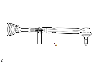
(b) Remove the LH tie rod end sub-assembly and lock nut.
12. REMOVE RH TIE ROD END SUB-ASSEMBLY
HINT:
Perform the same procedure as for the left side.