Installation
INSTALLATION
PROCEDURE
1. INSTALL LH TIE ROD END SUB-ASSEMBLY
(a) Install the lock nut and LH tie rod end sub-assembly onto the steering gear drive assembly until the marks are aligned. HINT: After adjusting the toe-in, tighten the lock nut. |
|
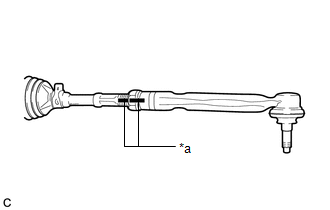
2. INSTALL RH TIE ROD END SUB-ASSEMBLY
HINT:
Perform the same procedure as for the left side.
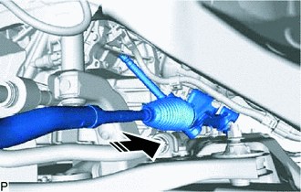
3. INSTALL STEERING LINKAGE ASSEMBLY
(a) Insert the power steering linkage assembly as shown in the illustration.
 |
Install in this direction |
(b) Align the protrusion of the steering linkage assembly with the hole in the No. 1 steering column hole cover sub-assembly, and install the No. 1 steering column hole cover sub-assembly onto the steering linkage assembly. HINT: Check that the No. 1 steering column hole cover sub-assembly is installed correctly. |
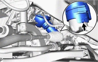 |
(c) Install the steering linkage assembly onto the front suspension crossmember sub-assembly with 2 new bolts and 2 new nuts.
Torque:
133 N·m {1,356 kgf·cm, 98 ft·lbf}
NOTICE:
- Do not turn the nut as it has a stopper. Tighten the bolt with the nut in place.
- Be sure to tighten the bolts starting from the left side of the vehicle.
(d) Install the wire harness clamp bracket onto the front suspension crossmember sub-assembly using the bolt.
(e) Connect the connector.
4. CONNECT LH TIE ROD END SUB-ASSEMBLY
(a) Connect the LH tie rod end sub-assembly to the LH steering knuckle with the nut. Torque: 49 N·m {500 kgf·cm, 36 ft·lbf} NOTICE:
|
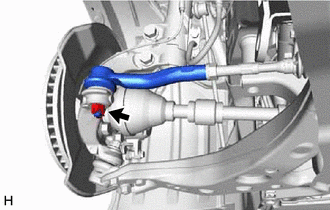 |
(b) Install a new cotter pin.
5. CONNECT RH TIE ROD END SUB-ASSEMBLY
HINT:
Perform the same procedure as for the left side.
6. CONNECT NO. 1 STEERING COLUMN HOLE COVER SUB-ASSEMBLY
(a) Engage the clip (B) with the vehicle body. |
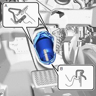 |
(b) Engage the clip (A) to reinstall the No. 1 steering column hole cover sub-assembly on the vehicle body.
NOTICE:
Take care not to damage the lip of the No. 1 steering column hole cover sub-assembly.
7. CONNECT THE NO. 2 STEERING INTERMEDIATE SHAFT ASSEMBLY
Click here
8. REINSTALL THE COLUMN HOLE COVER SOUND INSULATION SHEET
Click here
9. REINSTALL THE FRONT WHEELS
Click here
10. STABILIZE THE SUSPENSION
Click here
11. INSPECT AND ADJUST THE FRONT WHEEL ALIGNMENT
Click here