Removal
REMOVAL
PRECAUTION / NOTICE / HINT
The procedures required (adjustment, calibration, initialization or registration) that must be performed after parts have been removed, installed or replaced during brake pedal bracket assembly removal/installation are shown below.
Procedures Required After Replacement / Removal / Installation of PartsReplacement part or procedure | Required Procedure | Effect/Inoperative function when procedure not performed | Link |
|---|---|---|---|
Disconnect the cable from the negative (-) battery terminal. |
Initialize Back Door Lock |
Door Lock Control System |
 |
CAUTION:
Some service operations affect the SRS airbag system. Before starting any service operation, carefully read the precautions for the SRS airbag system.
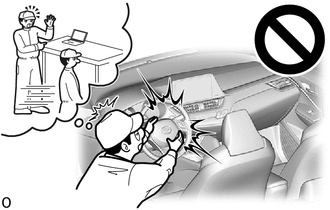
Click here
PROCEDURE
1. REMOVE INSTRUMENT PANEL SAFETY PAD SUB-ASSEMBLY
Click here
2. REMOVE STOP LIGHT SWITCH ASSEMBLY
Click here
3. REMOVE STOP LIGHT SWITCH MOUNTING ADJUSTER
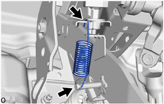
4. REMOVE BRAKE PEDAL RETURN SPRING
(a) Remove the brake pedal return spring from the brake pedal bracket assembly and push rod pin. |
 |
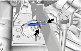
5. REMOVE PUSH ROD PIN
(a) Remove the clip and push rod pin to separate the brake pedal bracket assembly from the clevis of the brake master cylinder push rod. |
 |
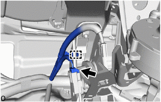
6. REMOVE BRAKE PEDAL BRACKET ASSEMBLY
(a) Disconnect the brake pedal load sensing switch connector. |
 |
(b) Release the clamp to separate the wire harness from the brake pedal bracket sub-assembly.
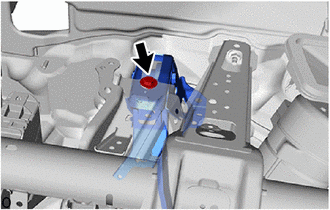
(c) Remove the bolt and separate the brake pedal bracket assembly from the instrument panel reinforcement assembly. |
 |
(d) Remove the 2 clips. |
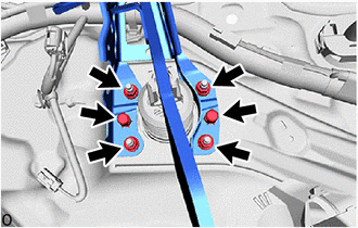 |
(e) Remove the 4 nuts and the brake pedal bracket assembly.
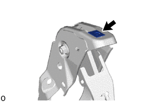
(f) Remove the nut from the brake pedal bracket assembly. |
 |
7. REMOVE BRAKE PEDAL COVER
(a) Remove the brake pedal cover from the brake pedal bracket assembly.