Removal
REMOVAL
PRECAUTION / NOTICE / HINT
The procedures required (adjustment, calibration, initialization or registration) after parts have been removed, installed or replaced during removal/installation of the horn button assembly are shown below.
Procedure Required After Replacing / Removing / Installing PartsReplacement part or procedure | Necessary Procedures | Effects / Inoperative Function When Necessary Procedure Not Performed | Link |
|---|---|---|---|
Disconnect the cable from the negative (-) battery terminal. |
Memorize Steering Angle Neutral Point |
Lane Departure Alert System (with Steering Control) |
 |
Pre-Collision System |
|||
Initialize Back Door Lock |
Door Lock Control System |
|
PROCEDURE
1. PRECAUTIONS
CAUTION:
Be sure to read the Precautions carefully before performing maintenance.
Click here
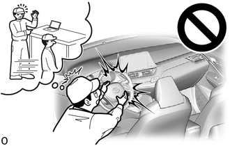
NOTICE:
After turning the ignition switch OFF, a waiting time may be required before disconnecting the cable from the negative (-) battery terminal. Therefore, be sure to read the precautions for disconnecting the cable from the negative (-) battery terminal before performing the work.
Click here
2. DISCONNECT THE CABLE FROM THE NEGATIVE BATTERY TERMINAL
Click here
CAUTION:
- Wait at least 90 seconds after disconnecting the cable from the negative (-) battery terminal to disable the SRS system.
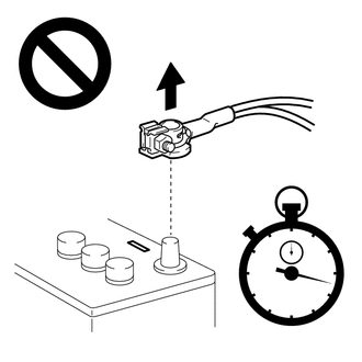
- If any Supplemental Restraint System (SRS) component is accidentally deployed, serious injury may result.
NOTICE:
When the cable has been disconnected, some systems must be reset after the cable is reconnected.
Click here
3. REMOVE HORN BUTTON ASSEMBLY
CAUTION:
When storing the horn button assembly, make sure the deployment side faces upward.
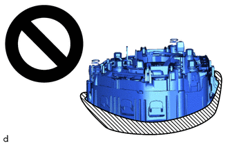
 |
Deployment side |
(a) Make sure the ignition switch is in the OFF position.
(b) Make sure the cable is disconnected from the negative (-) battery terminal.
CAUTION:
Wait at least 90 seconds after disconnecting the cable from the negative (-) battery terminal to disable the SRS system.
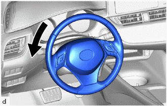
(c) Turn the steering wheel assembly 90° to the left. |
 |
(d) Wrap protective tape around a 6 mm hexagon wrench as shown in the illustration.
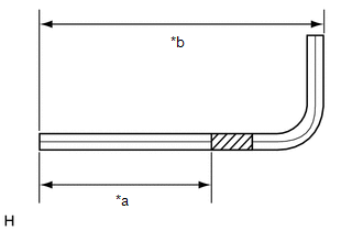
*a |
55 mm (2.17 in.) |
*b |
95 mm (3.74 in.) |
|
Protective tape |
HINT:
Use a 6 mm hexagon wrench with an arm length of approximately 95 mm (3.74 in.).
(e) Insert the 6 mm hexagon wrench into the access hole until the protective tape is at the position shown in the illustration.
HINT:
Be sure to insert the 6 mm hexagon wrench into the access hole located at the rear of the steering wheel assembly.
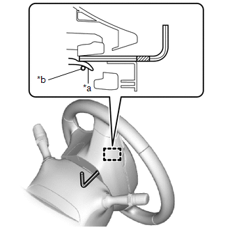
*a |
Case Tab |
*b |
Omega Spring |
|
Protective tape |
(f) Using the 6 mm hexagon wrench, push down the case tab to release the hook, as shown in the illustration. HINT: Push the case tab down to push the omega spring and release it from the hook. |
|
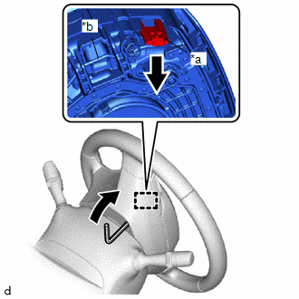
(g) Turn the steering wheel assembly 180° to the right. |
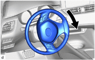 |
(h) Insert the 6 mm hexagon wrench into the access hole until the protective tape is at the position shown in the illustration.
HINT:
Be sure to insert the 6 mm hexagon wrench into the access hole located at the rear of the steering wheel assembly.
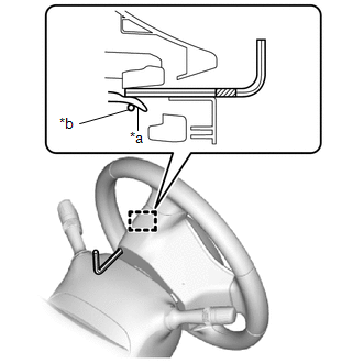
*a |
Case Tab |
*b |
Omega Spring |
|
Protective tape |
(i) Using the 6 mm hexagon wrench, push down the case tab to release the hook, as shown in the illustration. NOTICE: Hold the horn button assembly lightly to prevent it from falling. HINT: Push the case tab down to push the omega spring and release it from the hook. |
|
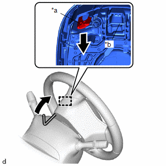
(j) Make sure each hook is released. HINT: If the hook is released, the spring will be visible at the position shown in the illustration. |
|
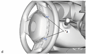
(k) Turn the steering wheel assembly 90° to the right. |
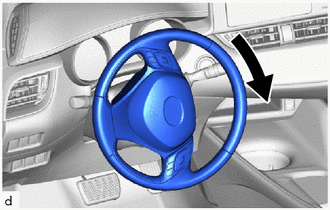 |
(l) Using a 6 mm hexagon wrench, push the case tab to release the hook, as shown in the illustration. NOTICE: Hold the horn button assembly lightly to prevent it from falling. HINT:
|
|
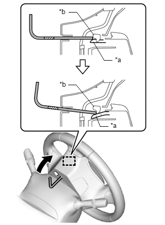
(m) Turn the steering wheel assembly 180° to the left to align the front wheels with the vehicle centerline.
NOTICE:
Do not drop the horn button assembly.
(n) Remove the horn button assembly from the steering wheel assembly and hold the horn button assembly with one hand.
NOTICE:
When removing the horn button assembly, be careful not to pull on the airbag wire harness.
(o) for single type:
(1) Disconnect the horn connector from the horn button assembly. |
|
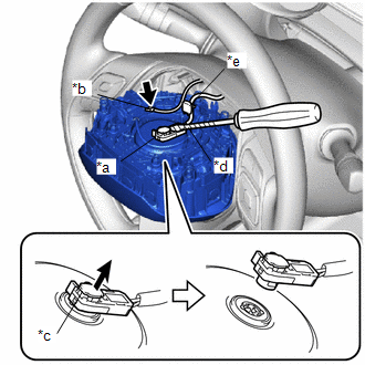
(2) Using a screwdriver with its tip wrapped in protective tape, unlock the airbag connector lock.
(3) Disconnect the airbag connector.
(4) Release the wire harness clamp to remove the horn button assembly
NOTICE:
When disconnecting any airbag connector, take care not to damage the airbag wire harness.
(p) for double type:
(1) Disconnect the horn connector from the horn button assembly. |
|
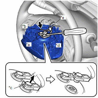
(2) Using a screwdriver with its tip wrapped in protective tape, release the 2 airbag connector locks.
(3) Disconnect the 2 airbag connectors.
(4) Release the wire harness clamp to remove the horn button assembly
NOTICE:
When disconnecting any airbag connector, take care not to damage the airbag wire harness.