Removal
REMOVAL
PRECAUTION / NOTICE / HINT
The procedures necessary (adjustment, calibration, initialization or registration) that must be performed after parts have been removed and installed or replaced during rear axle carrier subassembly removal/installation are shown below.
Procedures Required After Replacement / Removal / Installation of PartsReplaced Part or Performed Procedure | Required Procedure | Effect/Inoperative Function When Required Procedure Is Not Performed | Link |
|---|---|---|---|
Rear Wheel Alignment Adjustment |
|
|
 |
Removal/installation of rear left height control sensor sub-assembly*1 |
Initialize LH Headlight ECU Sub-assembly |
Automatic Headlight Leveling System |
|
Suspension, tires, etc. (Vehicle height changes due to suspension or tire replacement)*1 |
- *1: with height control sensor
HINT:
- Repeat the same procedure for the right side and the left side.
- The following procedure applies to the left side.
PROCEDURE
1. REMOVE REAR WHEEL
Click here
2. DISCONNECT REAR DISC BRAKE CALIPER ASSEMBLY
Click here
3. REMOVE REAR DISC
Click here
4. DISCONNECT SKID CONTROL SENSOR WIRE
Click here
5. REMOVE REAR AXLE HUB AND BEARING ASSEMBLY
Click here
6. REMOVE HOSE BRACKET
(a) Remove the bolt and hose bracket from the rear axle carrier subassembly. |
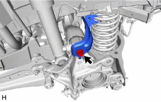 |
7. REMOVE REAR LEFT HEIGHT CONTROL SENSOR SUBASSEMBLY (with Height Control Sensor)
Click here
8. REMOVE REAR STABILIZER BAR LINK ASSEMBLY
Click here
9. REMOVE REAR COIL SPRING
Click here
10. REMOVE REAR COIL SPRING LOWER SEAT
Click here
11. REMOVE REAR SUSPENSION ARM ASSEMBLY NO. 1
Click here
12. REMOVE REAR AXLE CARRIER SUB-ASSEMBLY
(a) Remove the 2 bolts from the rear trailing arm assembly. |
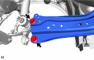 |
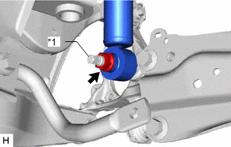
(b) Loosen the nut from the rear shock absorber assembly. NOTICE: Hold the rear axle carrier pin while turning the nut. |
|
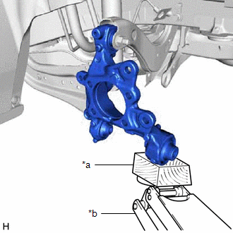
(c) Using a jack and a block of wood, support the rear axle carrier sub-assembly. NOTICE:
|
|
(d) Loosen the bolt (A). NOTICE: Do not turn the nut as it has a stopper. Loosen the bolt with the nut in place. |
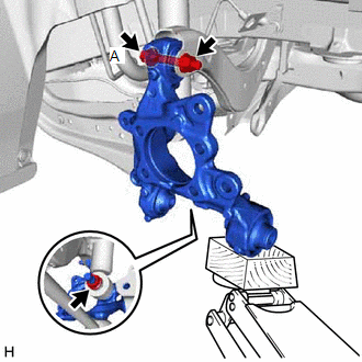 |
(e) Remove the 2 bolts and separate the rear trailing arm assembly from the rear axle carrier sub-assembly.
(f) Remove the nut and separate the rear shock absorber assembly from the rear axle carrier sub-assembly.
NOTICE:
Hold the rear axle carrier pin while turning the nut.
(g) Remove the bolt (A), the nut and the rear axle carrier sub-assembly from the rear upper control arm assembly.
NOTICE:
Do not turn the nut as it has a stopper. Loosen the bolt with the nut in place.