Power AUTO folding mirrors do not operate
DESCRIPTION
The outside rearview mirror switch assembly sends the mirror fold/unfold auto signal to the Main Body ECU (Multiplex Network Body ECU) when the outside rearview mirror fold switch on the outside rearview mirror switch assembly is in the AUTO position. The Main Body ECU (Multiplex Network Body ECU) folds or unfolds the outside rearview mirror assemblies based on the lock/unlock signal of all doors when the ignition switch is OFF.
WIRING DIAGRAM
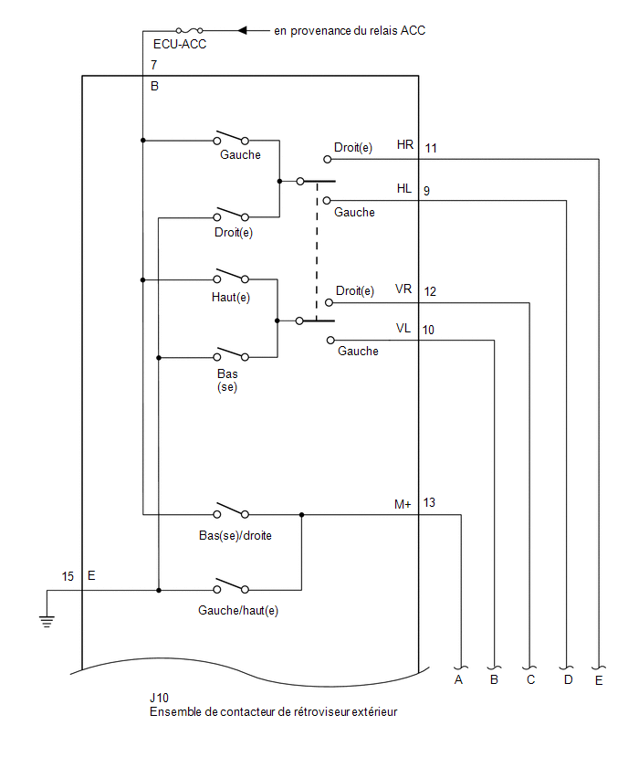
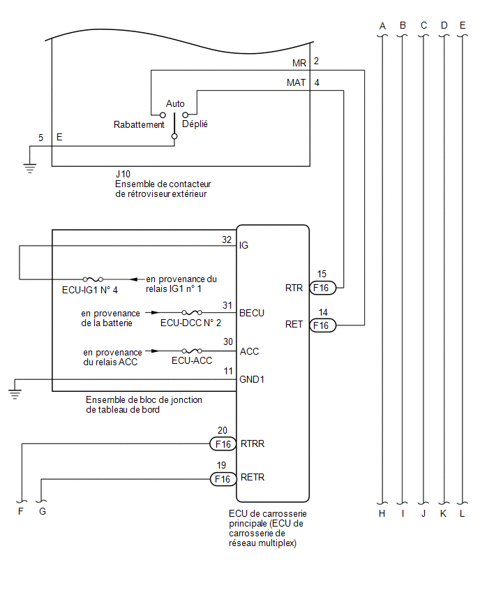
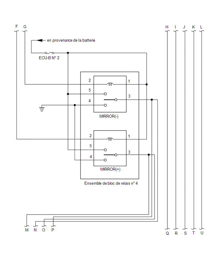
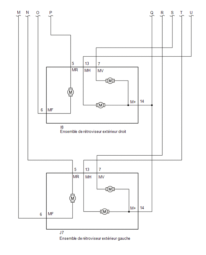
PRECAUTION / NOTICE / HINT
NOTICE:
- Check the fuses for the circuits related to this system before performing the following procedure.
- If the Main Body ECU (Multiplex Network Body ECU) has been replaced, refer to the registration section.*1
Click here

- *1: with Smart Key System
PROCEDURE
CHECK POWER MIRROR FOLDING FUNCTION
(a) Check the power mirror folding function.
Click here
OK:
The power mirror folding function operates normally.
| NG |  |
REFER TO DIAGNOSTIC PROCEDURE (power folding mirrors do not operate with power mirror folding switch) |
|

INSPECT DOOR LOCK CONTROL SYSTEM
(a) Check the door lock central control system.
Click here
OK:
The door lock central control system is normal.
| NG | |
GO TO DOOR LOCK CONTROL SYSTEM |
|
INSPECT WIRELESS DOOR LOCK CONTROL SYSTEM
(a) with Smart Key System
(1) Check the remote door lock central control system.
Click here
(b) without Smart Key System
(1) Check the remote door lock central control system.
Click here
OK:
The remote door lock central control system is normal.
Result:
Result | Proceed to |
|---|---|
OK (with Smart Key System) |
A |
OK (without Smart Key System) |
B |
NG (with smart key system) |
C |
NG (without smart key system) |
D |
| B | |
GO TO STEP 5 |
| C | |
GO TO WIRELESS DOOR LOCK CONTROL SYSTEM |
| D | |
GO TO WIRELESS DOOR LOCK CONTROL SYSTEM |
|
CHECK SMART KEY SYSTEM (for Entry Function)
(a) Check the Smart Key System (for Entry Function).
Click here
OK:
The Smart Key System (for Entry Function) is normal.
| NG | |
PROCEED TO SMART KEY SYSTEM (Entry Function) |
|
CHECK VALUE USING TECHSTREAM
(a) Connect the Techstream to the DLC3.
(b) Turn the ignition switch to ON.
(c) Turn on the Techstream.
(d) Select the following menus: Body Electrical / Main Body / Data List.
(e) Read the Data List by following the instructions on the Techstream.
Body Electrical > Main Body > Data ListTester display | Item | Range | Normal Condition | Diagnostic Note |
|---|---|---|---|---|
Auto Mirror SW |
Power Folding Outer Mirror Switch Signal |
OFF or ON |
OFF: Mirror switch not in AUTO position ON: Mirror switch in AUTO position |
- |
Auto Mirror SW
OK:
On the Techstream screen, ON or OFF is displayed accordingly.
| OK | |
REPLACE MAIN BODY ECU (MULTIPLEX NETWORK BODY ECU) |
|
INSPECT OUTSIDE REARVIEW MIRROR SWITCH ASSEMBLY
(a) Remove the outside rearview mirror switch assembly.
Click here
(b) Inspect the outside rearview mirror switch assembly.
Click here
| NG | |
REPLACE OUTSIDE REARVIEW MIRROR SWITCH ASSEMBLY |
|
CHECK WIRE HARNESS AND CONNECTOR (OUTSIDE REARVIEW MIRROR SWITCH ASSEMBLY - MAIN BODY ECU (MULTIPLEX NETWORK BODY ECU))
(a) Disconnect connector J10 from the outside rearview mirror switch assembly.
(b) Disconnect connector F16 from the Main Body ECU (Multiplex Network Body ECU).
(c) Measure the resistance according to the value(s) in the table below.
Standard resistance:
Tester Connection | Condition | Specified Condition |
|---|---|---|
J10-4 (MAT) - F16-15 (RTR) |
Always |
Below 1 Ω |
J10-4 (MAT) or F16-15 (RTR) - Body ground |
Always |
10 kΩ minimum |
| OK | |
REPLACE MAIN BODY ECU (MULTIPLEX NETWORK BODY ECU) |
| NG | |
REPAIR OR REPLACE HARNESS OR CONNECTOR |