Installation
INSTALLATION
PROCEDURE
1. INSPECT SPIRAL CABLE ASSEMBLY (without steering heater)
NOTICE:
If the steering angle sensor is installed on a misaligned spiral cable assembly, DTCs indicating an abnormal steering angle sensor value, such as DTC B1801, C1231 and C1433, will be stored and the problem cannot be corrected. If this occurs, replace the spiral cable assembly with sensor with a new one.
(a) Check whether the spiral cable assembly is centered. HINT: When the spiral cable assembly is centered, part (A) is at the top and the flat cable shown in the illustration is visible. |
|
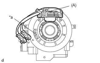
(b) If the spiral cable assembly is not centered, center it.
(1) While pressing the interlock as shown in the illustration, slowly turn the spiral cable assembly counterclockwise by hand until it stops. NOTICE:
|
|
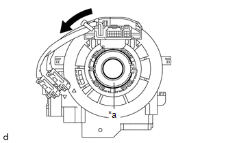
(2) While pressing the interlock shown in the illustration, turn the spiral cable assembly clockwise approximately 2.5 times in the position where the alignment marks are aligned and the flat cable shown in the illustration is visible. HINT: The spiral cable assembly can turn approximately 2.5 turns to the left and right from the center position. |
|
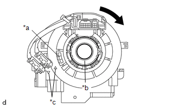
2. INSPECT SPIRAL CABLE ASSEMBLY (with steering heater)
NOTICE:
If the steering angle sensor is installed on a misaligned spiral cable assembly, DTCs indicating an abnormal steering angle sensor value, such as DTC B1801, C1231 and C1433, will be stored and the problem cannot be corrected. If this occurs, replace the spiral cable assembly with sensor with a new one.
(a) Check whether the spiral cable assembly is centered. HINT: When the spiral cable assembly is centered, part (A) is at the top and the flat cable shown in the illustration is visible. |
|
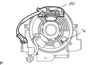
(b) If the spiral cable assembly is not centered, center it.
(1) While pressing the interlock as shown in the illustration, slowly turn the spiral cable assembly counterclockwise by hand until it stops. NOTICE:
|
|
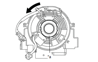
(2) While pressing the interlock shown in the illustration, turn the spiral cable assembly clockwise approximately 2.5 times in the position where the alignment marks are aligned and the flat cable shown in the illustration is visible. HINT: The spiral cable assembly can turn approximately 2.5 turns to the left and right from the center position. |
|
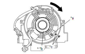
3. INSTALL SPIRAL CABLE SUB-ASSEMBLY WITH SENSOR
NOTICE:
- Do not replace the spiral cable sub-assembly with sensor while the battery is connected and the ignition switch is in the ON position.
- Do not rotate the spiral cable sub-assembly with sensor without locking the installed steering wheel assembly, with the battery connected and the ignition switch in the ON position.
- Make sure the steering wheel assembly is installed and in the straight-ahead position when checking the steering angle sensor.
(a) Make sure the ignition switch is in the OFF position.
(b) Make sure the cable is disconnected from the negative (-) battery terminal.
CAUTION:
Wait at least 90 seconds after disconnecting the cable from the negative (-) battery terminal to disable the SRS system.
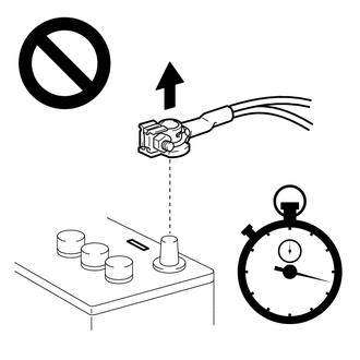
(c) Make sure the front wheels are aligned straight ahead.
(d) Engage the claws to install the spiral cable assembly with sensor. |
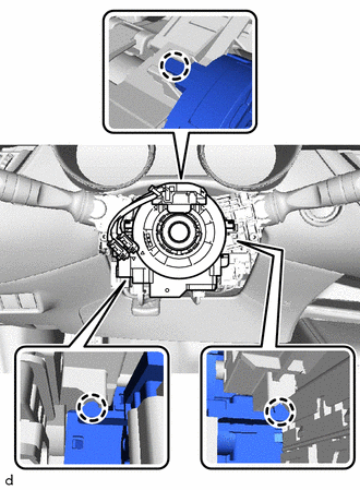 |
(e) Connect each connector.
4. INSTALL STEERING COLUMN UPPER SHROUD
Click here
5. INSTALL STEERING COLUMN LOWER SHROUD ASSEMBLY
Click here
6. ALIGN FRONT WHEELS STRAIGHT AHEAD
7. INSPECT AND ADJUST SPIRAL CABLE ASSEMBLY WITH SENSOR (without steering heater)
NOTICE:
Do not adjust the spiral cable assembly with sensor when the battery is connected and the ignition switch is ON.
(a) Make sure the ignition switch is in the OFF position.
(b) Make sure the cable is disconnected from the negative (-) battery terminal.
CAUTION:
Wait at least 90 seconds after disconnecting the cable from the negative (-) battery terminal to disable the SRS system.
(c) Check whether the spiral cable assembly with sensor is centered. HINT: When the spiral cable assembly with sensor is centered, part (A) is at the top and the flat cable shown in the illustration is visible. |
|
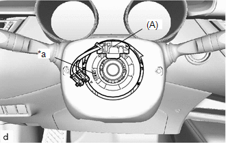
(d) If the spiral cable assembly with sensor is not centered, center it.
(1) While pressing the interlock as shown in the illustration, slowly turn the spiral cable assembly with sensor counterclockwise by hand until it stops. NOTICE:
|
|
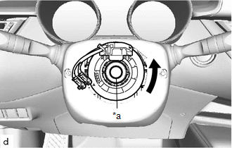
(2) While pressing the lock shown in the illustration, turn the clock spring with sensor clockwise approximately 2.5 turns from the center position, until part (A) is at the top and the flat cable shown in the illustration is visible. HINT: The clock spring with sensor can be turned approximately 2.5 turns to the left and to the right from the center position. |
|
8. CHECK AND ADJUST CLOCK SPRING WITH SENSOR (with steering heater)
NOTICE:
Do not adjust the spiral cable assembly with sensor when the battery is connected and the ignition switch is ON.
(a) Make sure the ignition switch is in the OFF position.
(b) Make sure the cable is disconnected from the negative (-) battery terminal.
CAUTION:
Wait at least 90 seconds after disconnecting the cable from the negative (-) battery terminal to disable the SRS system.
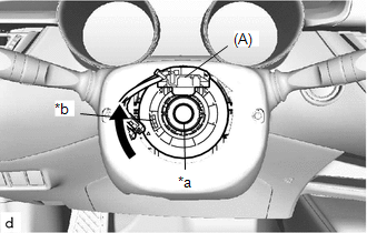
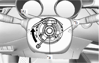
(c) Check whether the spiral cable assembly with sensor is centered. HINT: When the spiral cable assembly with sensor is centered, part (A) is at the top and the flat cable shown in the illustration is visible. |
|
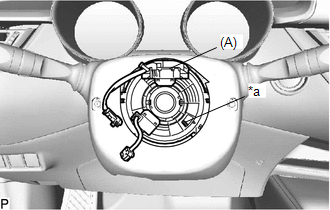
(d) If the spiral cable assembly with sensor is not centered, center it.
(1) While pressing the interlock as shown in the illustration, slowly turn the spiral cable assembly with sensor counterclockwise by hand until it stops. NOTICE:
|
|
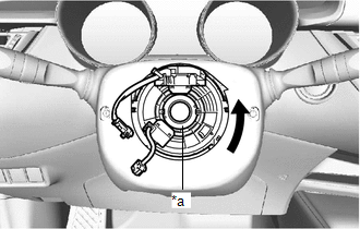
(2) While pressing the lock shown in the illustration, turn the clock spring with sensor clockwise approximately 2.5 turns from the center position, until part (A) is at the top and the flat cable shown in the illustration is visible. HINT: The clock spring with sensor can be turned approximately 2.5 turns to the left and to the right from the center position. |
|
9. INSTALL STEERING WHEEL ASSEMBLY
Click here