Installation
INSTALLATION
PRECAUTION / NOTICE / HINT
CAUTION:
The engine assembly with CVT transaxle assembly is very heavy. Be sure to follow the procedure described in the repair manual, otherwise the engine hoist may suddenly drop.
PROCEDURE
1. INSTALL TRANSMISSION BREATHER HOSE SUB-ASSEMBLY
HINT:
Perform this procedure only when replacement of the transmission breather hose sub-assembly is necessary.
(a) Apply genuine Toyota CVT FLUID FE to a new O-ring, then install it onto the No. 2 breather plug (CVT).
NOTICE:
Be careful not to damage or twist the O-ring.
(b) Install the No. 1 breather plug (CVT) and the No. 2 breather plug (CVT) onto the breather plug hose.
(c) Install the transmission breather hose sub-assembly onto the continuously variable transaxle assembly.
2. INSTALL STRAIGHT THREADED PLUG
HINT:
Perform this procedure only when replacement of the straight threaded plug is necessary.
(a) Install a new gasket and the straight threaded plug onto the continuously variable transaxle assembly.
Torque:
16.2 N·m {165 kgf·cm, 12 ft·lbf}
3. INSTALL AUTOMATIC TRANSMISSION CASE COVER
(a) Install the automatic transmission case cover onto the continuously variable transaxle assembly using the 2 clips.
4. INSTALL OIL COOLER ELBOW SUB-ASSEMBLY
(a) Install a new gasket and the oil cooler elbow sub-assembly onto the continuously variable transaxle assembly using the union bolt.
Torque:
23 N·m {230 kgf·cm, 17 ft·lbf}
NOTICE:
- Be sure to insert the painted (white) end of the No. 2 transmission oil cooler hose into the spool of the oil cooler elbow sub-assembly so that the marking faces the front of the vehicle.
- Be sure to clean and degrease the parts of the No. 2 transmission oil cooler hose and the oil cooler elbow sub-assembly that will be inserted.
(b) Install the No. 2 transmission oil cooler hose onto the oil cooler elbow sub-assembly, then slide the clamp into place to secure it.
5. INSTALL PIPE CONNECTOR
(a) Install a new O-ring onto the pipe connector.
(b) Install the pipe connector onto the continuously variable transaxle assembly.
Torque:
27 N·m {275 kgf·cm, 20 ft·lbf}
(c) Install the No. 1 transmission oil cooler hose onto the pipe connector, then slide the clamp into place to secure it.
6. INSTALL WIRE HARNESS CLAMP BRACKET
(a) Install the 3 wire harness clamp brackets onto the continuously variable transaxle assembly using the 3 bolts. Torque: 8 N·m {82 kgf·cm, 71 in·lbf} |
|
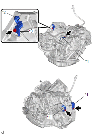
(b) Install the water bypass hose clamp onto the water hose bracket.
(c) Install the water hose bracket onto the continuously variable transaxle assembly using the bolt.
Torque:
10 N·m {102 kgf·cm, 7 ft·lbf}
7. INSTALL TRANSMISSION CONTROL CABLE BRACKET
(a) Install the transmission control cable bracket onto the continuously variable transaxle assembly using the 2 bolts.
Torque:
8 N·m {82 kgf·cm, 71 in·lbf}
8. INSTALL NO. 1 TRANSMISSION CONTROL CABLE BRACKET
(a) Install the No. 1 transmission control cable bracket to the CVT transaxle assembly with the 2 bolts.
Torque:
12 N·m {122 kgf·cm, 9 ft·lbf}
(b) Connect the clip to the No. 1 transmission control cable bracket.
9. INSTALL NO. 2 ENGINE POSITION ADJUSTING ROD
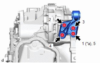
(a) Install the No. 2 engine position control rod to the CVT transaxle assembly with the 4 bolts in the order shown in the illustration. Torque: 44 N·m {449 kgf·cm, 32 ft·lbf} |
|
10. INSTALL FRONT SUSPENSION CROSSMEMBER SUB-ASSEMBLY
(a) Install the front suspension member sub-assembly to the No. 2 engine position adjusting rod with the bolt.
Torque:
170 N·m {1 734 kgf·cm, 125 ft·lbf}
11. INSTALL CVT OIL PUMP T-TYPE OIL SEAL
(a) Make sure there is no dust or foreign matter on your hands, then apply MP grease to the entire circumference of the lip of the new CVT oil pump T-type oil seal.
(b) Temporarily install the CVT oil pump T-type oil seal by pressing it onto the oil pump housing installation surface by hand.
NOTICE:
Make sure to install the CVT oil pump T-type oil seal in the correct direction.
(c) Clean the CVT oil pump T-type oil seal contact surface of the SST and the surrounding area.
SST: 09309-36010
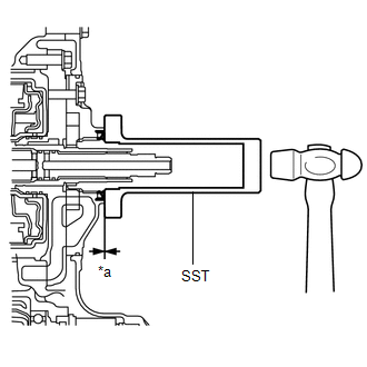
(d) Using the SST, evenly drive the CVT oil pump T-type oil seal until it is flush with the side surface of the oil pump housing. Standard depth: 0 to 0.5 mm (0 to 0.0196 in.) NOTICE:
HINT: The CVT oil pump T-type oil seal must be driven in 0 to 0.5 mm (0 to 0.0196 in.) as measured from the side surface of the oil pump housing. |
|
12. INSTALL TORQUE CONVERTER ASSEMBLY
(a) Turn the front oil pump drive gear so that the wide groove is at the top, and make an alignment mark on the transaxle case. NOTICE: Align the alignment mark with the wide groove of the transaxle case. |
|
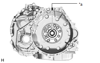
(b) Make an alignment mark on the torque converter assembly so that the position of its key is clearly indicated. |
|
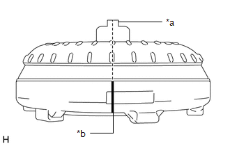
(c) Align the alignment mark on the transaxle case with the one on the torque converter assembly, then engage the input shaft splines with the turbine wheel splines. NOTICE:
|
|
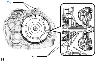
(d) Rotate the torque converter assembly approximately 180° and engage the stator shaft splines with the stator assembly. NOTICE:
|
|
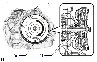
(e) Rotate the torque converter assembly approximately 180° again, align the alignment mark on the torque converter assembly with the one on the transaxle case, and insert the torque converter assembly key into the groove of the front oil pump drive gear. NOTICE:
|
|
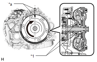
(f) Clean the drive plate and torque converter assembly bolt holes.
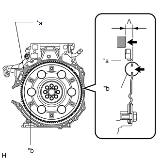
(g) Using a vernier caliper and a straightedge, measure the distance (A) between the continuously variable transaxle assembly contact surface of the engine assembly*a and the drive plate torque converter assembly contact surfaces*b. |
|
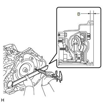
(h) Using a vernier caliper and a straightedge, measure dimension (B) as shown in the illustration, and make sure dimension (B) is greater than dimension (A) measured in the previous step. Standard: B = A + 1 mm (0.0394 in.) minimum NOTICE:
|
 |
13. INSTALL ENGINE ASSEMBLY
(a) Apply clutch spline grease to the crankshaft surface that contacts the torque converter assembly center piece. Clutch spline grease: Genuine Toyota clutch spline grease or equivalent Maximum Grease Quantity About 1 g (0.0353 oz.) |
|
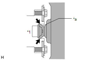
(b) Make sure the 2 impact dowels are installed on the engine assembly and are not damaged. |
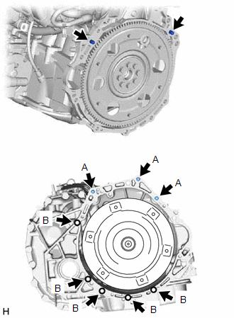 |
(c) Install the engine assembly to the CVT transaxle assembly with the 8 bolts.
Torque:
Bolt (A):
38 N·m {387 kgf·cm, 28 ft·lbf}
Bolt (B):
40 N·m {408 kgf·cm, 30 ft·lbf}
NOTICE:
- Make sure the wire harness or similar component is not pinched between the contact surfaces.
- Be careful not to apply excessive force when installing the continuously variable transaxle assembly.
- When attaching the continuously variable transaxle assembly to the engine assembly, be sure to insert the 2 impact dowels into the corresponding holes.
- Make sure the torque converter assembly rotates.
- When tightening the bolts, make sure the contact surfaces of the engine assembly and the continuously variable transaxle assembly are in contact with each other.
HINT:
- Bolt (A): Install from the continuously variable transaxle assembly side
- Bolt (B): Install from the engine assembly side
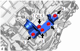
14. INSTALL TRANSVERSE ENGINE MOUNTING BRACKET
(a) Install the transverse engine mounting bracket using 5 new bolts. Torque: 41 N·m {418 kgf·cm, 30 ft·lbf} |
|
15. INSTALL ENGINE FLYWHEEL HOUSING SIDE COVER
Click here
16. INSTALL STARTER ASSEMBLY
Click here
17. CONNECT ENGINE WIRE
(a) Disengage the 5 clamps to disconnect the engine wire from the CVT transaxle assembly.
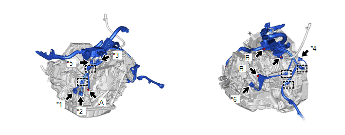
*1 |
Park/neutral position switch connector |
*2 |
Transmission cable connector |
*3 |
Transmission speed sensor (NIN) connector |
*4 |
Transmission speed sensor (NOUT) connector |
*5 |
Transmission speed sensor (NT) connector |
*6 |
Oil pressure sensor connector |
(b) Connect the engine cable to the CVT transaxle assembly with the 3 bolts and nut.
Torque:
Bolt (A):
8.5 N·m {87 kgf·cm, 75 in·lbf}
Bolt (B):
8 N·m {82 kgf·cm, 71 in·lbf}
Nut:
8 N·m {82 kgf·cm, 71 in·lbf}
(c) Reconnect the oil pressure sensor connector.
(d) Connect the transmission speed sensor (NOUT) connector.
(e) Connect the transmission speed sensor (NIN) connector.
(f) Connect the transmission speed sensor (NT) connector.
(g) Connect the transmission cable connector.
(h) Connect the park/neutral position switch connector.
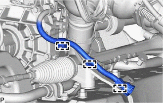
(i) Engage the 3 clamps to connect the engine wire to the front suspension member sub-assembly. |
 |
18. CONNECT NO. 5 WATER BYPASS HOSE
(a) Connect the No. 5 water bypass hose to the transaxle oil cooler and slide the clip to secure it.
NOTICE:
- Align each painted mark on the No. 5 water bypass hose with those on the transaxle oil cooler.
- Insert the No. 5 water bypass hose fully until it reaches the 2nd rib of each oil cooler pipe.
19. CONNECT NO. 3 WATER BYPASS HOSE
(a) Connect the No. 3 water bypass hose to the transaxle oil cooler and slide the clip to secure it.
NOTICE:
- Align each painted mark on the No. 3 water bypass hose with those on the transaxle oil cooler.
- Insert the No. 3 water bypass hose fully until it reaches the 2nd rib of each oil cooler pipe.
20. INSTALL ENGINE ASSEMBLY WITH TRANSMISSION
Click here
21. INSTALL DRIVE PLATE AND TORQUE CONVERTER ASSEMBLY SET BOLT
(a) Clean the threads of the 6 drive plate and torque converter assembly set bolts.
(b) Apply a few drops of adhesive to the 2 or 3 threads at the end of each of the 6 drive plate and torque converter assembly set bolts. Adhesive: Adhesive 1324, Three Bond 1324 Toyota genuine or equivalent NOTICE: To ensure proper installation of the 6 drive plate and torque converter assembly set bolts, apply adhesive to the 6 drive plate and torque converter assembly set bolts and install them within 10 minutes of applying the adhesive. |
|
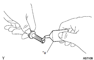
(c) Turn the crankshaft to access the installation positions of the 6 drive plate and torque converter assembly set bolts, and install each bolt while holding the crankshaft pulley with the SST.
Torque:
41 N·m {418 kgf·cm, 30 ft·lbf}
NOTICE:
Install the black bolt first, then the remaining 5 silver bolts.
22. INSTALL ENGINE FLYWHEEL HOUSING LOWER COVER
(a) Install the flywheel housing under cover.
23. RESET MEMORY
Click here