Installation
INSTALLATION
PROCEDURE
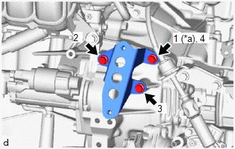
1. REINSTALL TRANSMISSION OIL COOLER BRACKET
(a) Install the transmission oil cooler bracket to the CVT assembly with the 3 bolts in the order shown in the illustration. Torque: 13.5 N·m {138 kgf·cm, 10 ft·lbf} |
|
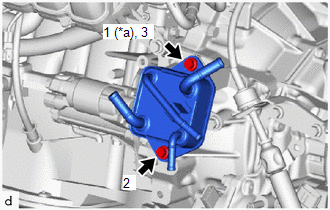
2. REINSTALL OIL COOLER
(a) Install the oil cooler to the transmission oil cooler bracket with the 2 bolts in the order shown in the illustration. Torque: 13.5 N·m {138 kgf·cm, 10 ft·lbf} |
|
3. CONNECT NO. 1 TRANSMISSION OIL COOLER HOSE
(a) Connect the No. 1 transmission oil cooler hose to the oil cooler and slide the clip to secure it.
NOTICE:
- Align each painted mark on the No. 1 transmission oil cooler hose with the one on the oil cooler.
- Fully insert the No. 1 transmission oil cooler hose onto the 2nd rib of each oil cooler pipe.
4. CONNECT NO. 2 TRANSMISSION OIL COOLER HOSE
(a) Connect the No. 2 transmission oil cooler hose to the oil cooler and slide the clip to secure it.
NOTICE:
- Align each painted mark on the No. 2 transmission oil cooler hose with the one on the oil cooler.
- Fully insert the No. 2 transmission oil cooler hose onto the 2nd rib of each oil cooler pipe.
5. CONNECT NO. 3 WATER BYPASS HOSE
(a) Connect the No. 3 water bypass hose to the oil cooler and slide the clamp to secure it.
NOTICE:
- Align each painted mark on the No. 3 water bypass hose with those on the oil cooler.
- Insert the No. 3 water bypass hose fully until it reaches the 2nd rib of each oil cooler pipe.
6. CONNECT NO. 5 WATER BYPASS HOSE
(a) Connect the No. 5 water bypass hose to the oil cooler and slide the clamp to secure it.
NOTICE:
- Align each painted mark on the No. 5 water bypass hose with those on the oil cooler.
- Insert the No. 5 water bypass hose fully until it reaches the 2nd rib of each oil cooler pipe.
7. INSTALL AIR CLEANER CASE SUB-ASSEMBLY
Click here
8. INSTALL AIR CLEANER COVER WITH AIR CLEANER HOSE
Click here
9. INSTALL AIR CLEANER INLET NO. 1
Click here
10. INSTALL RADIATOR SHROUD
Click here
11. ADD ENGINE COOLANT
Click here
12. CHECK FOR ENGINE COOLANT LEAKS
Click here
13. ADD CONTINUOUSLY VARIABLE TRANSAXLE FLUID
Click here
14. REINSTALL NO. 2 CYLINDER HEAD COVER
Click here
15. INSTALL REAR LEFT ENGINE UNDER COVER
Click here
16. REINSTALL NO. 1 ENGINE UNDER COVER
Click here