Instrument panel safety pad sub-assy
a. Some operations in this section may affect the SRS airbags. Prior to performing the corresponding operations, read the SRS airbag NOTICE
REPLACEMENTHINT:
- COMPONENTS:
- Installation is in the reverse order of removal.
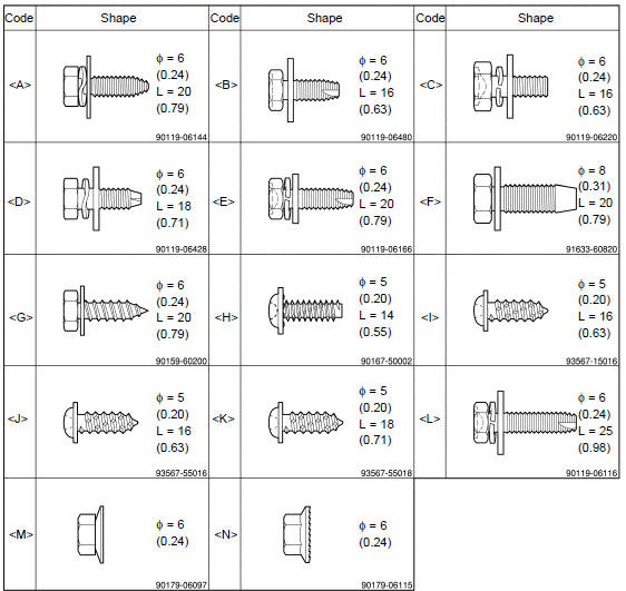
HINT: All bolts, screws and nuts relevant to installing and removing the instrument panel are shown along with their alphabet code in the table below.
mm (in.) (L = Length)
- DISCONNECT BATTERY NEGATIVE TERMINAL
- REMOVE STEERING WHEEL COVER LOWER No.2
- REMOVE STEERING WHEEL COVER LOWER No.3
- REMOVE HORN BUTTON ASSY
- REMOVE STEERING WHEEL ASSY SST 09950−50013 (09951−05010, 09952−05010, 09953−05020, 09954−05021)
- REMOVE INSTRUMENT CLUSTER FINISH PANEL
a. Disengage the 4 clips and remove the instrument cluster finish panel.
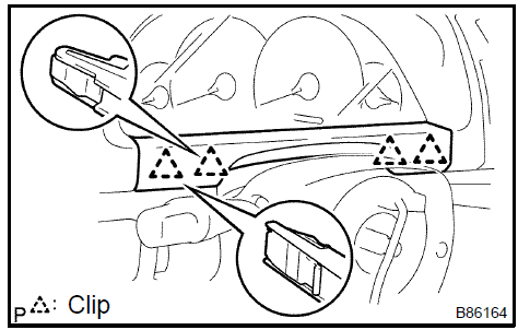 M Remove instrument cluster finish panel
- REMOVE STEERING COLUMN COVER
- REMOVE HEADLAMP DIMMER SWITCH ASSY
- REMOVE WINDSHIELD WIPER SWITCH ASSY
- REMOVE COMBINATION METER ASSY
- Remove the 2 screws and disengage the 2 clips.
- Pull out the combination meter assy, then disconnect the connectors.
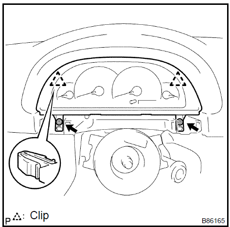 Remove combination meter assy 12. REMOVE FRONT DOOR SCUFF PLATE LH
a. Disengage the 7 claws and 4 clips then remove the front door scuff plate LH.
 Remove front door scuff plate LH 13. REMOVE FRONT DOOR SCUFF PLATE RH
HINT: Use the same procedures for the RH side and LH side.
14. REMOVE INSTRUMENT PANEL UNDER COVER SUB−ASSY No.1- Disengage the 3 claws and pin.
- Remove the instrument panel under cover sub−assy No.1.
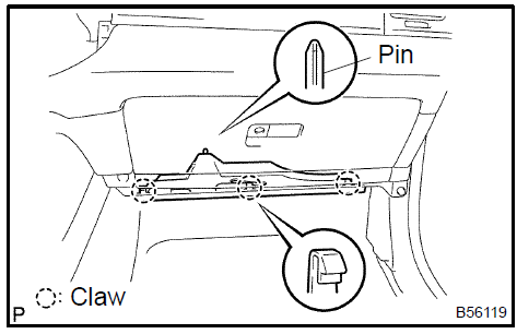 Remove instrument panel under cover sub-assy No.1 15. REMOVE COWL SIDE TRIM SUB−ASSY LH
- Remove the clip.
- Disengage the 2 clips and remove the cowl side trim sub− assy LH.
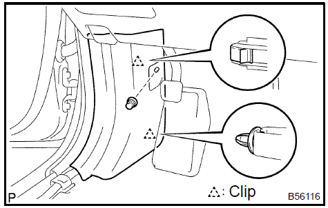 Remove cowl side trim sub-assy LH 16. REMOVE COWL SIDE TRIM SUB−ASSY RH
HINT: Use the same procedures for the RH side and LH side.
17. REMOVE INSTRUMENT PANEL COIN BOX SUB−ASSYa. Disengage the claw and remove the instrument panel coin box sub−assy.
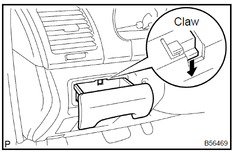 Remove instrument panel coin box sub-assy 18. REMOVE INSTRUMENT PANEL SUB−ASSY UPPER
- Disconnect the hood lock control cable.
- Using a screwdriver, open the instrument panel sub−assy upper cover.
HINT: Tape the screwdriver tip before use.
- TMC made: Remove the bolt <E> and 2 screws <K>.
- TMMK made: Remove the bolt <D> and 2 screws <H>.
- Disengage the 3 clips.
- Disconnect the connectors and remove the instrument panel sub−assy upper.
 Remove instrument panel sub-assy upper 19. REMOVE INSTRUMENT PANEL INSERT LOWER
- TMC made: Remove the 4 bolts <L>.
- TMMK made: Remove the 4 bolts <A>.
- Disengage the 2 claws and remove the instrument panel insert lower.
 Remove instrument panel insert lower 20. REMOVE AIR CONDITIONER CONTROL ASSEMBLY (AUTO AIR CONDITIONING)
- Put in a hand from the position indicated in the illustration and push out the clip with fingers.
- Remove the remaining clips, disengage the claws, and then take off the air conditioner control assembly.
- Perform this procedure wearing the protection gloves.
- Do not use any tools to avoid damage to the instrument panel safety pad sub−assembly.
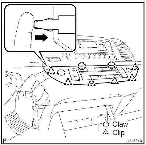 Remove air conditioner control assembly (auto air conditioning) 21. REMOVE AIR CONDITIONING PANEL SUB−ASSY (MANUAL AIR CONDITIONING)
HINT: Use the same procedures for the air conditioner control assembly and air conditioning panel sub−assy.
22. REMOVE INSTRUMENT CLUSTER FINISH PANEL SUB−ASSY CENTER- Remove the 4 bolts.
- Using a moulding remover, disengage 5 clips, remove the instrument cluster finish panel sub−assy center with radio receiver assy, then disconnect the connectors.
 Remove instrument cluster finish panel sub-assy center 23. REMOVE GLOVE COMPARTMENT DOOR PAD
a. Using a screwdriver, remove the glove compartment door pad.
HINT: Tape the screwdriver tip before use.
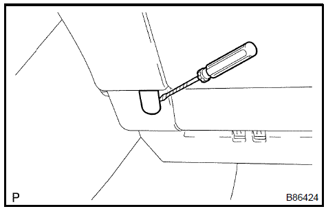 Remove glove compartment door pad 24. REMOVE INSTRUMENT PANEL SUB−ASSY LOWER
- TMC made: Remove the bolt <E> and 4 screws <K>.
- TMMK made: Remove the bolt <D> and 4 screws <H>.
- Disengage the claw and clip and remove the instrument panel sub−assy lower.
 Remove instrument panel sub-assy lower 25. REMOVE SHIFT LEVER KNOB SUB−ASSY (MANUAL TRANSAXLE)
a. Turn the shift lever knob sub−assy counterclockΩise and remove the shift lever knob sub−assy.
26. REMOVE CONSOLE PANEL UPPER REARa. Foot parking brake: Using a moulding remover, disengage the claw and 8 clips and remove the console panel upper rear.
HINT: Set the shift lever in the N position.
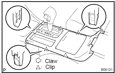 Remove console panel upper rear
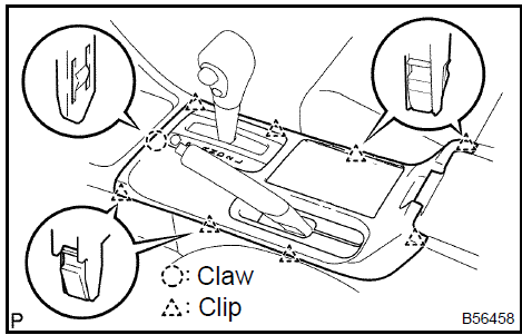
b. Hand parking brake: Using a moulding remover, disengage the claw and 8 clips and remove the console panel upper rear.
HINT: Set the shift lever in the N position (Automatic transaxle).
- TMC made: Remove the 2 bolts <B> and 2 screws <I>.
- TMMK made: Remove the 2 bolts <C> and 2 screws <H>.
- Disengage the 2 claws and remove the RR console box.
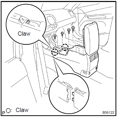 Remove rr console box 29. REMOVE CONSOLE PANEL SUB−ASSY
- Using a moulding remover, disengage the 4 clips.
- Disconnect the connectors and remove the console panel sub−assy.
HINT: Set the shift lever in the N position (Automatic transaxle).
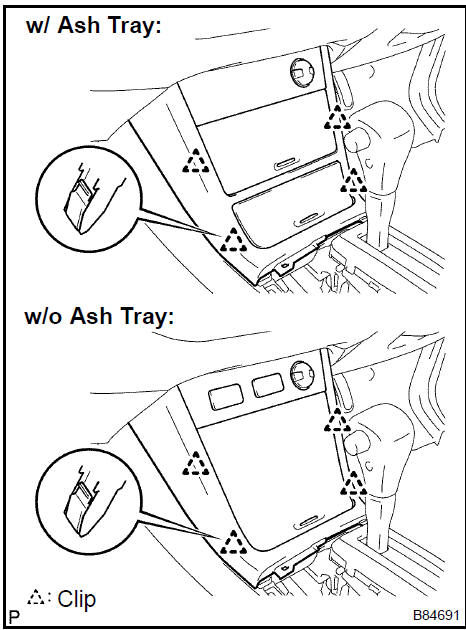 Remove console panel sub-assy 30. REMOVE CONSOLE BOX FRONT
- Remove the 2 nuts <M>.
- Disengage the 2 claws and remove the console box front.
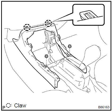 Remove console box front 31. REMOVE INSTRUMENT PANEL FINISH PANEL LOWER CENTER
- TMC made: Remove the 2 screws <K>.
- TMMK made: Remove the 2 screws <H>.
- Disengage the 4 clips and remove the instrument panel finish panel lower center.
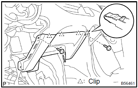 Remove instrument panel finish panel lower center 32. REMOVE FRONT PILLAR GARNISH LH (W/O CURTAIN SHIELD AIR BAG)
a. Using a moulding remover, disengage the 2 clips and 2 claws then remove the front pillar garnish LH.
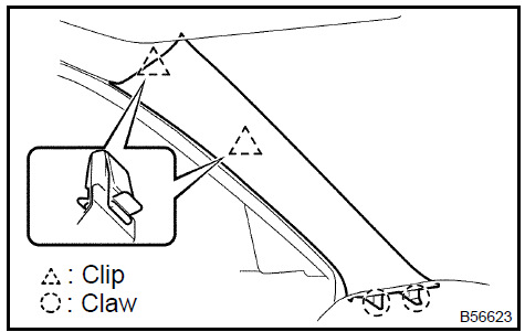 Remove front pillar garnish LH (W/O curtain shield air bag) 33. REMOVE FRONT PILLAR GARNISH LH (W/ CURTAIN SHIELD AIR BAG)
a. Using a screwdriver, open the cover and remove the bolt.
HINT: Tape the screwdriver tip before use.
b. Using a moulding remover, disengage the clip and 2 claws then remove the front pillar garnish LH.
 Remove front pillar garnish LH (W/ curtain shield air bag) 34. REMOVE FRONT PILLAR GARNISH RH (W/O CURTAIN SHIELD AIR BAG)
HINT: Use the same procedures for the RH side and LH side.
35. REMOVE FRONT PILLAR GARNISH RH (W/ CURTAIN SHIELD AIR BAG)HINT: Use the same procedures for the RH side and LH side.
36. REMOVE INSTRUMENT PANEL SPEAKER PANEL SUB−ASSY No.2a. Using a screwdriver, disengage the 2 clips and 2 claws.
HINT: Tape the screwdriver tip before use.
b. Remove the instrument panel speaker panel sub−assy No.2.
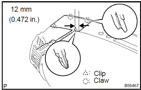 Remove instrument panel speaker panel sub-assy No.2 37. REMOVE INSTRUMENT PANEL SPEAKER PANEL SUB−ASSY
HINT: Use the same procedures for the instrument panel speaker panel sub−assy and instrument panel speaker panel sub−assy No.2.
- REMOVE FRONT No.2 SPEAKER ASSY
- DISCONNECT PASSENGER AIRBAG CONNECTOR
- REMOVE INSTRUMENT PANEL SAFETY PAD CAP
a. Using a screwdriver, remove the instrument panel safety pad cap.
HINT: Tape the screwdriver tip before use.
 Remove instrument panel safety pad cap 41. REMOVE INSTRUMENT PANEL SAFETY PAD SUB−ASSY W/FRONT PASSENGER AIRBAG ASSY
- TMC made: Remove the 2 screws <G> <I>, nut <N> and 5 bolts <A> <F>.
- TMMK made: Remove the 2 screws <H> or <J> <G>, nut <M> and 4 bolts <A> <F>.
- Disconnect the connectors.
- Disengage the 5 pins and remove the instrument panel safety pad sub−assy with front passenger airbag assy.
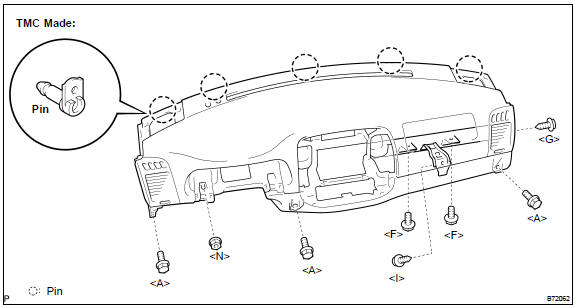
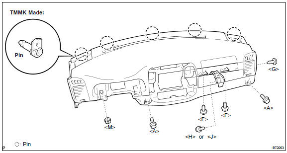
- Disengage the 3 clips and 3 claws.
- Remove the instrument panel register assy No.2.
- Disengage the 3 clips and 3 claws.
- Remove the instrument panel register assy No.1.
a. Disengage the 4 claws and remove the glove box lamp assy.
45. REMOVE AUTOMATIC LIGHT CONTROL SENSORa. Using a screwdriver, remove the automatic light control sensor.
HINT: Tape the screwdriver tip before use.
 Remove automatic light control sensor 46. REMOVE COOLER (SOLAR SENSOR) THERMISTOR (AUTO AIR CONDITIONING)
a. Remove the cooler (solar sensor) thermistor.
NOTICE: Do not pry the cooler (solar sensor) thermistor off from the upper side. Remove cooler (solar sensor) thermistor (auto air conditioning)
- REMOVE SPARE SWITCH HOLE COVER (MANUAL AIR CONDITIONING)
- REMOVE SIDE DEFROSTER NOZZLE DUCT No.2
- TMC made: Remove the screw <I> and side defroster nozzle duct No.2.
- TMMK made: Remove the screw <H> or <J> and side defroster nozzle duct No.2.
- TMC made: Remove the screw <I> and side defroster nozzle duct No.1.
- TMMK made: Remove the screw <H> or <J> and side defroster nozzle duct No.1.
- TMC made: Remove the 5 screws <I> and defroster nozzle assy.
- TMMK made: Remove the 5 screws <H> or <J> and defroster nozzle ass
- TMC made: Remove the 2 screws <I> and heater to register duct No.1.
- TMMK made: Remove the 2 screws <H> or <J> and heater to register duct No.1.
- TMC made: Remove the 2 screws <I> and heater to register duct No.3.
- TMMK made: Remove the 2 screws <H> or <J> and heater to register duct No.3.
- TMC made: Remove the screw <I> and heater to register duct No.2.
- TMMK made: Remove the screw <H> or <J> and heater to register duct No.2.
a. Disengage the 5 clips and remove the defroster nozzle garnish No.1.
55. REMOVE INSTRUMENT PANEL PIN No.1- TMC made: Remove the 2 screws <I> and 2 instrument panel pin No.1.
- TMMK made: Remove the 2 screws <H> or <J> and 2 instrument panel pin No.1.
- REMOVE FRONT PASSENGER AIRBAG ASSY
- INSTALL FRONT PASSENGER AIRBAG ASSY
- INSTALL INSTRUMENT PANEL SAFETY PAD SUB−ASSY W/FRONT PASSENGER AIRBAG ASSY
- Engage the 5 pins.
- Connect the connectors.
- TMC made: Install the instrument panel safety pad sub−assy w/ front passenger aibag assy with the 2 screws <G> <I>, nut <N>, and 5 bolts <A> <F>. Torque: Bolt <F> : 20 N·m
- TMMK made: Install the instrument panel safety pad sub−assy w/ front passenger airbag assy with the 2 screws <H> or <J> <G>, nut <M>, and 4 bolts <A> <F>. Torque : Bolt <F>: 20 N·m
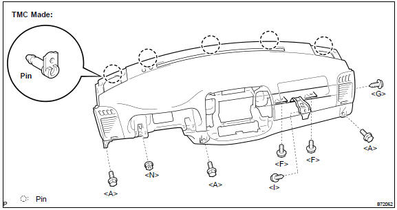
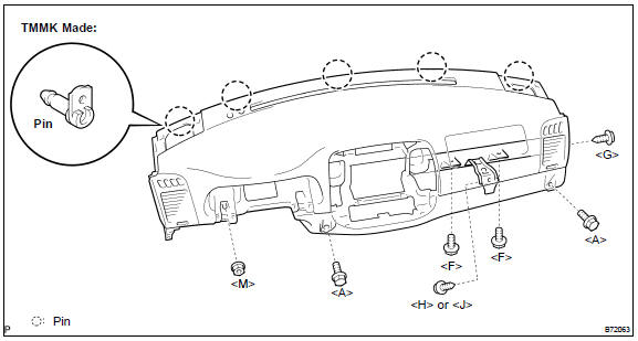
- Engage the 2 claws and clip.
- Install the front pillar garnish with the bolt. Torque: 7.5 to 20 N·m (77 to 204 kgf·cm, 67 in.·lbf to 14 ft·lbf)
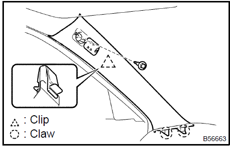 Install front pillar garnish LH (W/ curtain shield air bag) 60. INSTALL FRONT PILLAR GARNISH RH (W/ CURTAIN SHIELD AIR BAG)
HINT: Use the same procedures for the RH side and LH side.
- CENTER SPIRAL CABLE
- INSTALL STEERING WHEEL ASSY
- INSTALL HORN BUTTON ASSY
- INSPECT HORN BUTTON ASSY
- INSPECT SRS WARNING LIGHT
Test yourself
A quick Toyota Camry quiz: every answer comes with an explanation and a link to the manual page.