Washer Fluid Level Warning Switch Circuit
DESCRIPTION
When the washer fluid level is lower than a certain level, a warning message is displayed on the combination meter assembly.
WIRING DIAGRAM
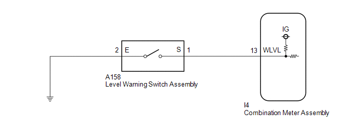
PROCEDURE
READ VALUE USING GTS (COMBINATION METER)
(a) Read the Data List according to the display on the GTS.
Body Electrical > Combination Meter > Data ListTester Display | Measurement Item | Range | Normal Condition | Diagnostic Note |
|---|---|---|---|---|
Washer Level Warning Switch |
Washer fluid level warning switch |
OFF or ON |
OFF: Washer fluid level not low ON: Washer fluid level low |
- |
Washer Level Warning Switch
OK:
The GTS display changes correctly in response to the washer fluid level.
| OK |  |
REPLACE COMBINATION METER ASSEMBLY |
|

INSPECT LEVEL WARNING SWITCH ASSEMBLY
HINT:
This check should be performed with the level warning switch assembly installed on the washer jar.
(a) Remove the level warning switch assembly.
(b) Fill the washer jar with washer fluid. |
|
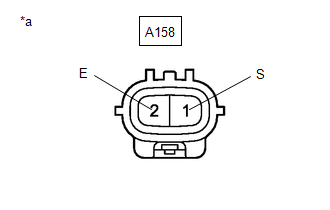
(c) Measure the resistance according to the value(s) in the table below.
Standard Resistance:
Tester Connection | Condition | Specified Condition |
|---|---|---|
A158-1 (S) - A158-2 (E) |
Fluid volume is 600 to 800 cc (36.6 to 48.8 cu.in.) or higher* |
10 kΩ or higher |
Fluid volume is 600 to 800 cc (36.6 to 48.8 cu.in.) or lower* |
Below 1 Ω |
HINT:
*: The level warning switch assembly begins operating when the fluid volume is 600 to 800 cc (36.6 to 48.8 cu.in.) depending on the vehicle condition.
| NG | |
REPLACE LEVEL WARNING SWITCH ASSEMBLY |
|
CHECK HARNESS AND CONNECTOR (LEVEL WARNING SWITCH ASSEMBLY - COMBINATION METER ASSEMBLY)
(a) Disconnect the I4 combination meter assembly connector.
(b) Measure the resistance according to the value(s) in the table below.
Standard Resistance:
Tester Connection | Condition | Specified Condition |
|---|---|---|
A158-1 (S) - I4-13 (WLVL) |
Always |
Below 1 Ω |
A158-1 (S) or I4-13 (WLVL) - Body ground |
Always |
10 kΩ or higher |
| NG | |
REPAIR OR REPLACE HARNESS OR CONNECTOR |
|
CHECK HARNESS AND CONNECTOR (LEVEL WARNING SWITCH ASSEMBLY - BODY GROUND)
(a) Measure the resistance according to the value(s) in the table below.
Standard Resistance:
Tester Connection | Condition | Specified Condition |
|---|---|---|
A158-2 (E) - Body ground |
Always |
Below 1 Ω |
| OK | |
REPLACE COMBINATION METER ASSEMBLY |
| NG | |
REPAIR OR REPLACE HARNESS OR CONNECTOR |