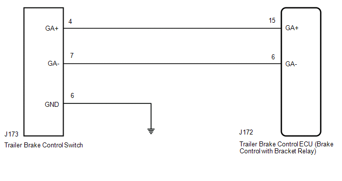
With the ignition switch turned to ON and the IG terminal voltage from 11 to 14 V, an open circuit occurs continuously in the GAIN (+) selection button internal circuit or wire harness and connector stuck ON for 60 seconds or more
Trailer brake control switch
Trailer brake control ECU (Brake control with bracket relay)
Harness or connector
C14A2
Gain Rocker Switch (-) Circuit
31
With the ignition switch turned to ON and the IG terminal voltage from 11 to 14 V, an open circuit occurs continuously in the GAIN (-) selection button internal circuit or wire harness and connector stuck ON for 60 seconds or more
Trailer brake control switch
Trailer brake control ECU (Brake control with bracket relay)
Harness or connector
WIRING DIAGRAM
PROCEDURE
INSPECT TRAILER BRAKE CONTROL SWITCH
(a) Turn the ignition switch off.
(b) Remove the trailer brake control switch.
Click here
(c) Inspect the trailer brake control switch.
Click here
OK:
The trailer brake control switch operates normally.
NG
REPLACE TRAILER BRAKE CONTROL SWITCH
OK
CHECK HARNESS AND CONNECTOR (BRAKE CONTROL WITH BRACKET RELAY - TRAILER BRAKE CONTROL SWITCH)
(a) Disconnect the J172 trailer brake control ECU (brake control with bracket relay) connector.
(b) Measure the resistance according to the value(s) in the table below.
Standard Resistance:
Tester Connection
Condition
Specified Condition
J172-6 (GA-) - J173-7 (GA-)
Always
Below 1 Ω
J172-6 (GA-) or J173-7 (GA-) - Body ground
Always
10 kΩ or higher
J172-15 (GA+) - J173-4 (GA+)
Always
Below 1 Ω
J172-15 (GA+) or J173-4 (GA+) - Body ground
Always
10 kΩ or higher
J173-6 (GND) - Body ground
Always
Below 1 Ω
NG
REPAIR OR REPLACE HARNESS OR CONNECTOR
OK
TRAILER BRAKE PROBLEM CHECK
(a) Check the GAIN (+/-) selection button (trailer brake control switch) operation condition.
OK:
he GAIN (+/-) selection button (trailer brake control switch) has not been pushed and held for 1 minute or more.