Running gear, axles, steering
Assembly overview - drive shaft
In this manual: Running gear, axles, steering
~2min read
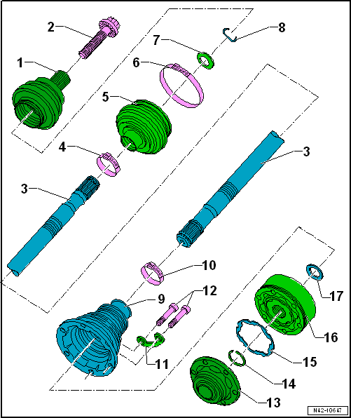
| 1 - | Outer constant velocity joint |
Renew only as complete unit
Removing → Fig..
Installing: drive onto shaft to stop using plastic hammer
Distribute grease evenly in joint
Checking → Chapter
| 2 - | Bolt |
Renew after removing
Before fitting, clean the threads in the CV joint using a thread tap.
200 N·m +180° → Chapter
| 3 - | Drive shaft |
Allocation → Electronic Parts Catalogue.
| 4 - | Clamp |
Renew after removing
Tightening → Fig.
| 5 - | Boot |
Check for splits and chafing
Material: Hytrel (polyester elastomer)
| 6 - | Clamp |
Renew after removing
Tightening → Fig.
| 7 - | Dished spring |
With inner splines
Installation position → Fig.
| 8 - | Retaining ring |
Renew after removing
Insert in groove in shaft
| 9 - | Boot for constant velocity joint |
Material: Hytrel (polyester elastomer)
Without breather hole
Check for splits and chafing
Drive off constant velocity joint with a drift
Coat sealing surface of constant velocity joint with -D 454 300 A2- before installing.| 10 - | Clamp |
Renew after removing
Tightening → Fig.
| 11 - | Locking plate |
| 12 - | Multi-point socket head bolt |
Renew after removing
Initially tighten diagonally to 10 N·m and then tighten diagonally to specified torque.40 N·m
| 13 - | Cover |
Renew after removing
Always renew
Pressing off → Fig.
| 14 - | Retaining ring |
Renew after removing
Remove and install with circlip pliers -VW 161 A-.
| 15 - | Seal |
Renew after removing
Adhesive surface on constant velocity joint must be free of oil and grease!
| 16 - | Inner constant velocity joint |
Renew only as complete unit
Distribute grease evenly in joint
Pressing off → Fig.
Pressing on → Fig.
Checking → Chapter
| 17 - | Dished spring |
With inner splines
Installation position → Fig.
Test yourself
A quick Volkswagen Golf quiz: every answer comes with an explanation and a link to the manual page.
Was this page helpful?