Running gear, axles, steering

Removing and installing wheel bearing housing

~4min read
0408012016020012089N·mlb·ft
Tightening torque found on this page
Removing and installing wheel bearing housing

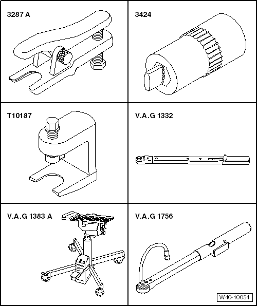
Special tools and workshop equipment required

Ball joint puller -3287A-

Spreader -3424-

Ball joint puller -T10187-

Torque wrench -V.A.G 1332-

Engine and gearbox jack -V.A.G 1383 A-

Angle wrench -V.A.G 1756-


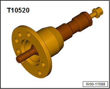
Press tool -T10520-

Removing

  • Remove bolt for drive shaft → Chapter.
Caution Wheel bearings must not be subjected to load after bolt securing drive shaft to wheel hub has been loosened. If wheel bearings are loaded with weight of vehicle, bearing will be damaged. This reduces the service life of the wheel bearing. It is not permissible to loosen drive shaft bolt more than 90° if vehicle is standing on its wheels. Do not attempt to move the vehicle without the drive shafts fitted as this would damage the wheel bearing. If a vehicle nevertheless has to be moved, comply with the following:

Install an outer joint instead of the drive shaft.

Tighten outer joint to 120 N·m.

  • Loosen wheel bolts.
  • Raise vehicle.
  • Remove wheel.
  • Detach brake caliper and tie to body with wire → Brake system; Rep. gr.46.
  • Remove ABS speed sensor → Brake system; Rep. gr.45.
  • Remove brake disc → Brake system; Rep. gr.46
  • Detach bracket for brake line and electrical wiring from wheel bearing housing and move clear.
Removing and installing wheel bearing housing
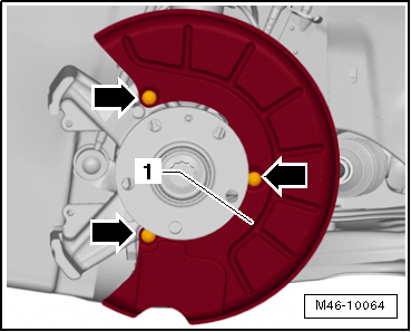
  • Remove splash plate -1- from wheel bearing housing -arrows-.
  • Loosen nut on track rod ball joint but do not remove completely.
Removing and installing wheel bearing housing
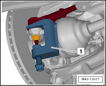
  • Press track rod off wheel bearing housing using ball joint puller -T10187--1-.
Caution

Leave nut screwed on a few turns to protect thread on pin.

  • Unscrew nut, and remove track rod upwards from wheel bearing housing.

Vehicles with vehicle level sender

Removing and installing wheel bearing housing
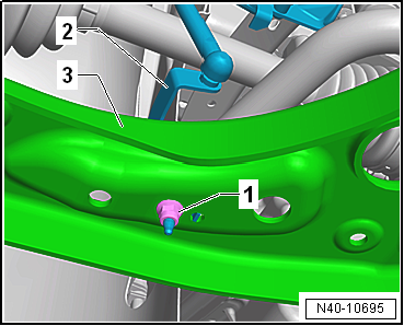
  • Unscrew nut -1-.
  • Pull bracket -2- for front left vehicle level sender -G78- and/or for front right vehicle level sender -G289- out of suspension link -3-, as applicable

Continuation for all vehicles

Removing and installing wheel bearing housing
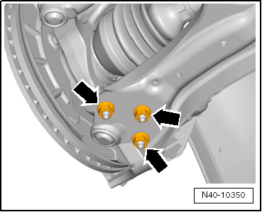
  • Remove nuts -arrows-.
  • Pull swivel joint out of suspension link.
  • Pull outer joint of drive shaft out of wheel hub.
If drive shaft cannot be pulled out of the wheel bearing by hand, use press tool -T10520-.
Removing and installing wheel bearing housing

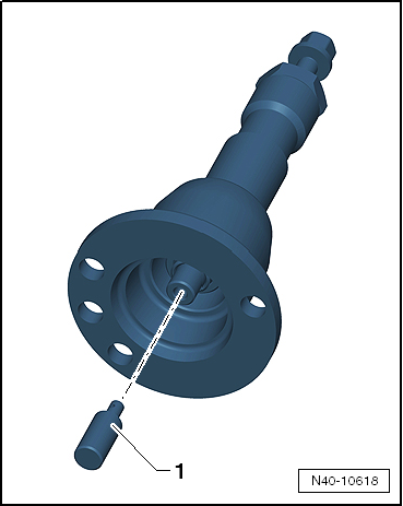
Before using press tool -T10520- ensure that thrust piece -1- is inserted.

Using press tool -T10520-:

Removing and installing wheel bearing housing
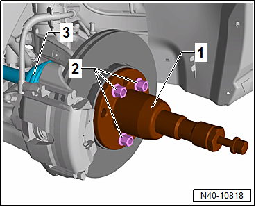
  • To be able to press out drive shaft -3-, secure press tool -T10520--1- to wheel hub using 3 wheel bolts -2-.
Removing and installing wheel bearing housing
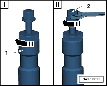
  • It is essential to follow specified sequence.
I - Tighten knurled nut -1- hand-tight.
II - Turn only bolt -2- using a spanner in order to press out drive shaft with press tool -T10520-.
Note At the end of the procedure or for pressing out drive shaft further the spindle must be moved to its original position in order to deploy the hydraulic force!
  • Secure drive shaft to body with wire.
  • Position engine and gearbox jack -V.A.G 1383 A- under wheel bearing housing.
Removing and installing wheel bearing housing
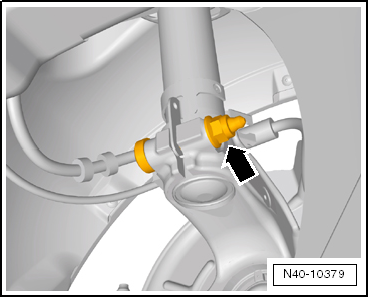
  • Remove threaded connection between wheel bearing housing and suspension strut -arrow-.
Removing and installing wheel bearing housing
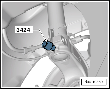
  • Insert spreader -3424- in slot in wheel bearing housing.
Note Make sure that the spreader -3424- is only inserted into the wheel bearing housing. Insert sufficiently to ensure that the metal tab of the suspension strut is not damaged.
  • Turn ratchet handle through 90° and detach from spreader -3424-.
  • Pull wheel bearing housing from suspension strut.
Note If wheel bearing housing is renewed, swivel joint must be transferred. Always use new nuts.

Installing

Install in reverse order of removal, observing the following:

Note

Lever on vehicle level sender must face towards outside of vehicle.

Thread of vehicle level sender must be screwed into outer hole in suspension link. Retaining lug for vehicle level sender must engage in inner hole in order to guarantee correct installation position.
  • On vehicles with vehicle level sender, carry out basic settings for wheel damper electronics → Vehicle diagnostic tester.

Specified torques

→ Chapter „Assembly overview - wheel bearing assembly“

→ Chapter „Assembly overview - lower suspension link, swivel joint“

→ Chapter „Assembly overview - suspension strut, upper suspension link“

→ Chapter „Assembly overview - drive shaft“

→ Chapter „Assembly overview - front vehicle level senders“

→ Chapter „Torque settings for wheel bolts“

Speed sensor bolt → Brake system; Rep. gr.45

Bolts for splash plate, brake caliper, brake disc → Brake system; Rep. gr.46

Removing and installing wheel bearing housing

Test yourself

A quick Volkswagen Golf quiz: every answer comes with an explanation and a link to the manual page.