Heater Core, Removing and Installing
Special tools and workshop equipment required
- Shop Crane - Drip Tray -VAS6208-
- Hose Clamps - Up To 25mm -3094-
- Commercially available compressed-air gun
- Engine Bung Set -VAS6122-
Removing
- Depending on the engine, the air intake hose between the air filter and turbocharger also needs to be removed.
- Place the Shop Crane - Drip Tray -VAS6208- under the engine.
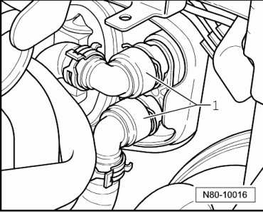
The cooling system is under pressure when the engine is warm. There is a risk of scalding from hot steam and coolant. Burns on the skin and other parts of the body are possible.Wear safety gloves.Wear protective eyewear.Reduce the pressure: cover the coolant reservoir cap with a cloth and carefully open.
- Clamp the coolant hoses -1- using the Hose Clamps - Up To 25mm -3094- and disconnect the coolant hoses from the heater core.
- Connect a section of the hose -A- to the upper connection on the heater core.
- Hold a container -B- under the lower connection -C-.
- Using a compressed air gun, carefully blow out any coolant still inside the heater core into the container -B-.

- Loosen the bolt -1- on the connection flange between the heat exchanger connections, but do not remove it.

Note
By loosening the screw -1-, the coolant pipes are loosened and it is easier to remove the heater core.
- Remove the driver footwell cover.
- Remove the left footwell vent.
- Remove the bolts -A- and the cover -B-.
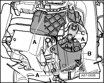
Note
- There are different versions of cover -B-.
- The illustration shows the version with Auxiliary Heater Heating Element -Z35-.
- If the temperature door lever -C- is at a position that hinders access to the upper screw -A-. Change the position of the temperature door using the hot and fresh air controls; on vehicles with Climatronic (e.g. "Hi" setting).
- Cover the carpet in the area under the heater core with waterproof foil and water absorbing paper.
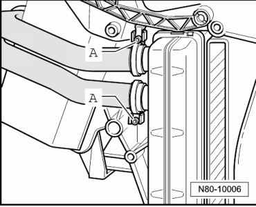
- Open the clamps -A- and remove the coolant pipes from the heat exchanger.
- Remove the heater core from the heater.
Installing
Install in reverse order of removal while noting the following:
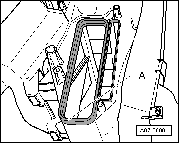
- Check seals -A and B- on the heat exchanger for damage.
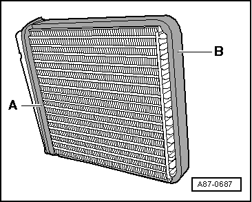
Note
- An incorrectly glued seal can roll up into heater when sliding in the heater core.
- Cold air may flow past the heater core if the seal is damaged or not properly fitted.
- Check the heater (while the heater core is removed) through the shaft -A- for the heater core, for debris.
- Remove any dirt or coolant which has leaked out of the heater (for example, after removing a leaking heater core).
- Install the heater core into the heater.
- Coat sealing rings -1- with coolant before installing.
- Install the seals -1- into the connection on the heater core.

Note
- Ensure sealing rings are installed on the proper side, as shown in the illustration.
- If pipe clamps are deformed, replace them.
- Attach the coolant pipes to the heater core.
- Pipe clamps -A- must be able to be twisted slightly when installing onto the coolant pipes.
- Pipe clamps -A- must be installed as shown in the illustration.
- Tighten the pipe clamps -A- to 2 N·m.
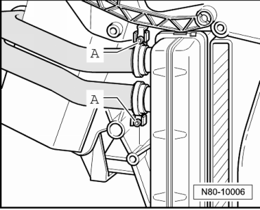
- Check the clamps -A- for proper seating after tightening the screws. They must completely enclose the flange on the heater core and coolant pipe and must not come in contact with other components.
- Tighten the connection flange bolt -1- between the heat exchanger connections to 2 N·m.

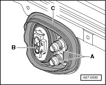
- Make sure the grommet -C- fits correctly inside the plenum chamber bulkhead.
- Seal flange for coolant pipes to heater core -A- and for expansion valve (to evaporator, only in vehicles with A/C system) -B- at pass-through of grommet -C- with silicon adhesive sealant if necessary to prevent water from penetrating.
Note
- The seals must be replaced.
- Replace all the coolant after replacing the heater core.
- Check coolant circuit for leaks, pay particular attention to the connection between coolant hoses and heater core.
Evaporator Temperature Sensor -G308-, Removing and Installing
Special tools and workshop equipment required
- Trim Removal Wedge -3409-
- Vehicle diagnostic tester
Removing
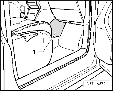
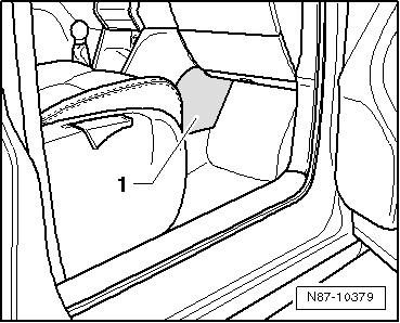
- Remove the cover -1- in the front passenger footwell.
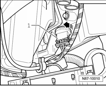
- Disconnect the connector -1- from the Evaporator Temperature Sensor -G308-.
- Turn the Evaporator Temperature Sensor -G308- in the direction of the -arrow- and remove it.
Installing
Install in reverse order of removal.
Partition, Removing and Installing
Removing
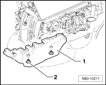
- Remove the plastic screws -2- and the partition -1-.
Installing
Install in reverse order of removal.
Fresh Air Blower Series Resistor with Fuse -N24-, Removing and Installing
Removing
Risk of burns from hot surfaces on the fresh Air Blower Series Resistor with Fuse.It is possible to burn hands.Wear safety gloves.
Perform the following work first:
- Remove the partition from the heater.
- Disconnect the connector -1- from the Fresh Air Blower Series Resistor With Fuse -N24-.
- Push the retainer in the direction of the arrow and remove the Fresh Air Blower Series Resistor with Fuse -N24- from the heater.

Installing
Install in reverse order of removal.
Evaporator Vent Temperature Sensor -G263-, Removing and Installing
Special tools and workshop equipment required
- Trim Removal Wedge -3409-
- Vehicle Diagnostic Tester
Removing
- Remove the cover -1- in the front passenger footwell.
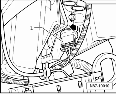
- Remove the connector from the Evaporator Temperature Sensor -G308- or Evaporator Vent Temperature Sensor -G263--1-.
- Turn the Evaporator Temperature Sensor -G308- or Evaporator Vent Temperature Sensor -G263- in the direction of the -arrow- and remove it.
Installing
Install in reverse order of removal.
Condensation Water Drain, Checking
Checking
- Remove the trim panel in the front passenger footwell.
The discharge point for the condensation water drain hose is located under the carpet and the noise insulating foam.
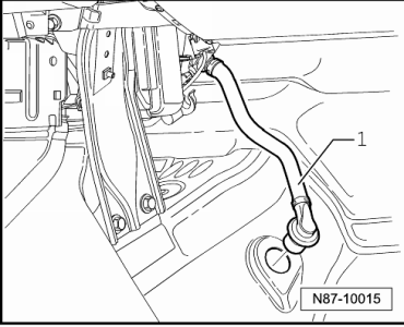
Note
- The condensation water drain hose -1- must be able to be connected to the heater and a/c unit connection without pre-tension.
- The condensation water drain hose must sit securely on the heater and A/C unit connection condensation water drain.
Glove Compartment Cooling, Removing and Installing
Removing
- Remove the glove compartment.
- Remove the hose for the glove compartment cooling -1- from the valve -3-.
- Remove the hose for the glove compartment cooling -1- from the connection -2- on the heater and A/C unit.
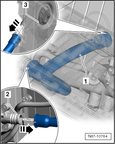
Installing
- Install the hose for the glove compartment cooling in reverse order. When doing this, note the following:
- The hose fits in only one position. The notch must align with the tab.
- The hose must not get bent or squeezed.
Test yourself
A quick Volkswagen Tiguan quiz: every answer comes with an explanation and a link to the manual page.