Unit mounting
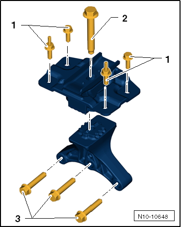
Assembly overview - Unit mounting
Engine mounting
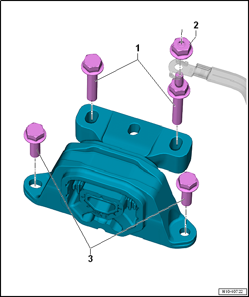

Transmission mounting
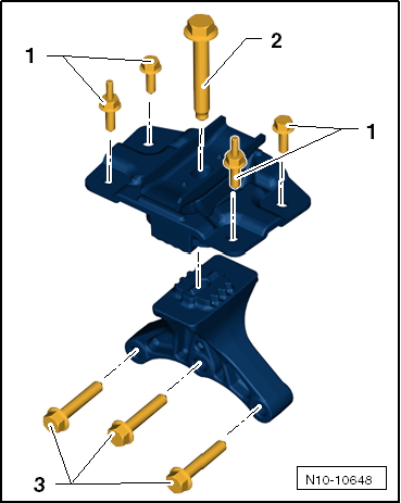
Torque strut
Risk of accident. The bolted connection -arrow- must not be loosened.

Removing and installing engine mount
Required Special Tools, Test and Measuring Equipment and Auxiliary Items
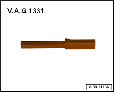
- Torque Wrench -V.A.G 1331-
- Support the engine in installed position.
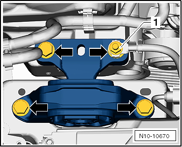
- Unscrew earth strap -1-.
Unscrew fastening bolts -arrows- and remove the engine-side unit mount.
Reassembly is carried out in the reverse order of removal.

Note
- The engine mount must be pulled into position without tension.
- The final tightening torque may only be applied once the vehicle has been fully lowered to the ground.
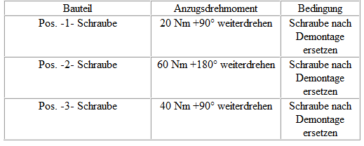
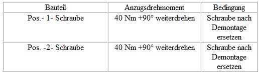
Tightening torques
- Engine mount "Assembly overview - Unit mounting"
Removing and installing transmission mount
Removing
- Remove battery carrier → Electrical system.
- Support the engine in installed position.
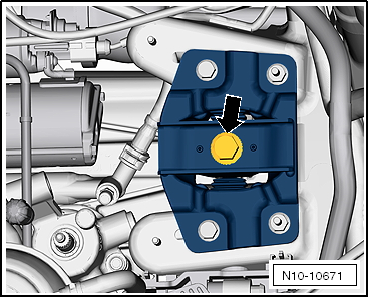
- Unscrew bolt -arrow- from transmission mount.
- Unscrew bolts -1- and remove transmission mount.
Installing
Installation is carried out in the reverse order, observing the following:
Risk of damage to the threads in the transmission support from inserting bolts at an angle.
- Raise the transmission with the spindle of the support fixture until the transmission support contacts the transmission mount.
- Check adjustment of the unit mounts.
- Remove support fixture -10 - 222 A- from the engine.
Tightening torques
- "Adjusting unit mounts"
- → Electrical system
Removing and installing torque strut
- Remove fastening bolts -arrows- of the torque strut.
Risk of accident. The screw connection -1- must not be loosened.
Installing
Installation is carried out in the reverse order, observing the following:
Tightening torques
- "Assembly overview - Unit mounting"

Support engine in installed position
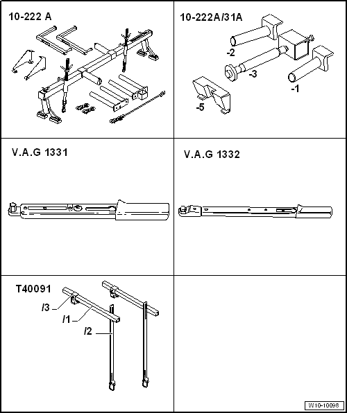
Required Special Tools, Test and Measuring Equipment and Auxiliary Items
- Support fixture -10-222 A-
- Adapter -10 - 222 A /3-
- Adapter -10 - 222 A /31-1-
- Adapter -10 - 222 A /31-2-
- Connector -T40091/3-
- Square tube -T40091/1-
- Support -10 - 222 A /31-3-
- Adapter -10 - 222 A /31-5-
- Torque Wrench -V.A.G 1331-
- Torque Wrench -V.A.G 1332-
Work sequence
- Unclip coolant hoses from the timing belt cover.
- Remove air filter housing. "Removing and installing air filter housing"
- Wiper arms → Electrical System.
- Cowl panel cover → Body assembly work, exterior.

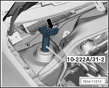
- Place adapter -10 - 222 A /31-1- and adapter -10 - 222 A /31-2- on the strut holders.
The webs -arrow- point toward the engine compartment.
- If fitted, pull hood seal off lock carrier.
- Place holder -10 - 222 A /31-5- on the lock carrier at the right headlight.
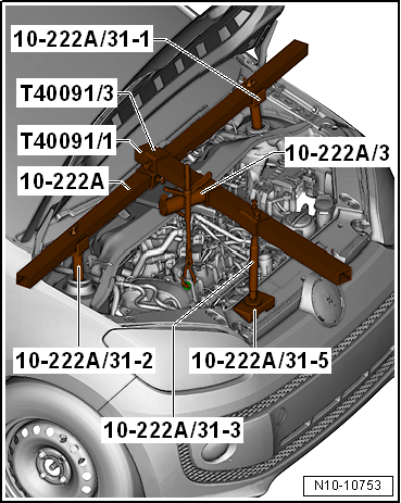
- Slide connector -T40091/3- onto support device -10-222 A-.
- Bolt support device -10-222 A- to adapter -10 - 222 A /31-1- and adapter -10 - 222 A /31-2-.
- Connect square tube -T40091/1- to support device -10-222 A-.
- Place square tube over support -10 - 222 A /31-3- onto adapter -10 - 222 A /31-5-.
- Screw spindle to adapter -10 - 222 A /3-.
- Hook spindle into the right mounting eye on the engine.
- Lightly preload engine/transmission unit using the spindle.
Adjust engine mounts
Work sequence
- Support the engine in installed position.
- Replace engine mount bolts one at a time, if not already done, and screw in finger-tight.
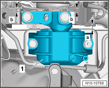
- Distance -a- between engine mount and right side member must be the same at front and rear.
- Tighten engine mount bolts.
Installation is carried out in reverse order.
Tightening torques
- "Checking engine mount adjustment"
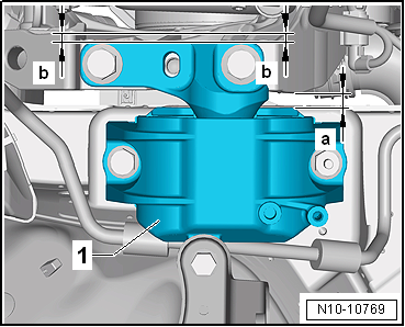
Check engine mount adjustment
Work sequence
- Distance -a- between engine mount and right side member must be the same at front and rear.
Only if there is a noise complaint (engine or transmission knocks against the side member when cornering)
- Adjust engine mounting.