Removing and installing engine
Removing engine
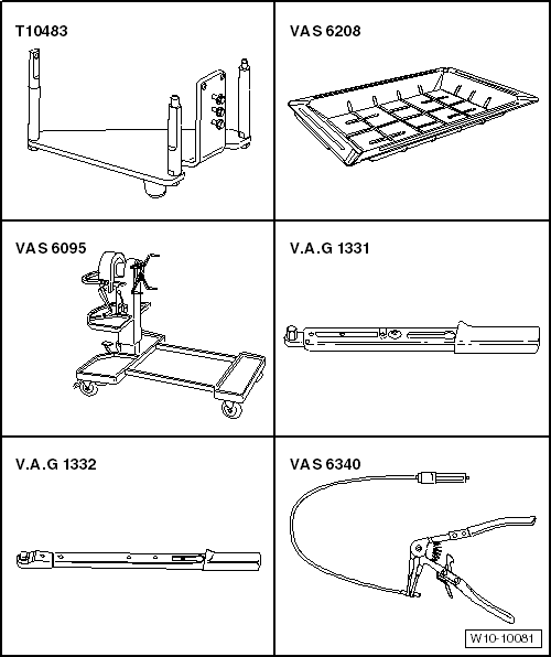
Required Special Tools, Test and Measuring Equipment and Auxiliary Items
- Engine holder -T10483-
- Drip pan for workshop crane -VAS 6208-
- Engine and transmission holder -VAS 6095-
- Torque Wrench -V.A.G 1331-
- Torque Wrench -V.A.G 1332-
- Hose clamp pliers -VAS 6340-
- Commercially available step ladder (not illustrated)
- Adapter -T10480- (not illustrated)

Note
The engine is removed downward together with the transmission.
- Check whether a coded radio is installed. If so, obtain the anti-theft code beforehand.
- Disconnect battery → Electrical system.
- Remove battery and battery carrier → Electrical system.
- Loosen or cut cable ties.
- Remove air filter housing “Removing and installing air filter housing”.
- Remove engine control module “Removing and installing engine control module -J623-”.
- Unclip wiring harness at the mounting points and secure it to the engine.
- Open and close the coolant expansion tank cap to release pressure from the cooling system.
- Unlock and disconnect fuel supply line -1- and vent line -2- → Fuel supply - petrol engines.
- Open cable routing -3- and remove hoses.
- Plug lines so that no dirt can enter the fuel system.
- Drain coolant “Draining and refilling coolant”.
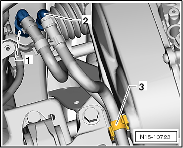
- Disconnect all coolant hoses -1- from the coolant pump.
- Disconnect connector -1- from the expansion tank.

- Press locking lugs in direction of arrow and pull expansion tank upward.
- Disconnect coolant hose -2-.

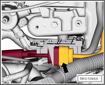
- Disconnect the two plug connections -arrow- and unclip the wiring harness.
- Disconnect plug connections of the lambda sensors -arrows-.
- Remove shift linkage from transmission.
Remove starter motor → Electrical system.
- Remove clutch slave cylinder.
Vehicles with air conditioning

Note
- The air conditioning lines are not opened.
- To avoid damage to the condenser and to the refrigerant lines and hoses.
- Do not overstretch, kink or bend lines and hoses.
- Remove serpentine belt “Removing and installing serpentine belt”.
- Remove A/C compressor: → Heating, air conditioning.
- Secure A/C compressor to the lock carrier.
Lines must not be kinked.
Continuation for all vehicles
- Unscrew fastening bolts -1-.

- Unscrew fastening bolt on catalytic converter and remove bracket -2-.

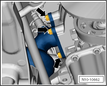
- Unscrew fastening nuts -arrows- and pull catalytic converter off the studs.
Risk of accident. The screw connection -1- must not be loosened.
- Remove fastening bolts -arrows- of the torque strut.
- Remove right and left drive shafts → Suspension, axles, steering.
- Move lock carrier into service position → Body assembly work, exterior.
In direction of travel, right
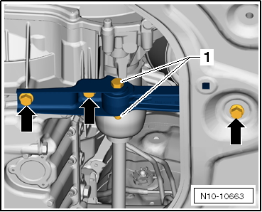
- Screw together 2 adapters -T10480--1- and -2- each and install.
In direction of travel, left

- Install one adapter -T10480--1- and -2- each.
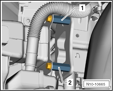
To lower engine and transmission, engine holder -T10483- with adapters -/1-, -/2- and -/3- is required.
- Press engine holder -T10483- into the bores in the crankcase -arrows- as far as it will go.

- First tighten bolts -1- finger-tight.
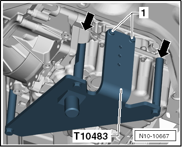
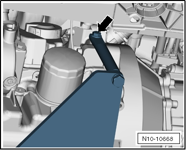
- First tighten bolt -arrow- finger-tight.
- Tighten bolts -arrows- to 20 N·m.
- Also tighten all remaining bolts to 20 N·m.
- Attach engine and transmission lifter -V.A.G 1383 A- to engine holder -T10416-.
- Lift engine and transmission slightly with engine and transmission lifter -V.A.G 1383 A-.

Note
To remove the fastening bolts, use step ladder -VAS 5085-.
- Unscrew earth strap -1-.

Unscrew fastening bolts -arrows- and remove the engine-side unit mount.
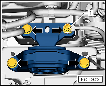
- Unscrew transmission-side unit mount -arrow-.

Note
The unit must be guided carefully when lifting out to avoid damage to the body.
- Carefully lower engine and transmission downward.
To carry out installation work, secure the engine to the engine and transmission holder -VAS 6095-.
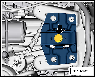
Separating engine and transmission
Separating engine and transmission, vehicles with manual transmission
Required Special Tools, Test and Measuring Equipment and Auxiliary Items
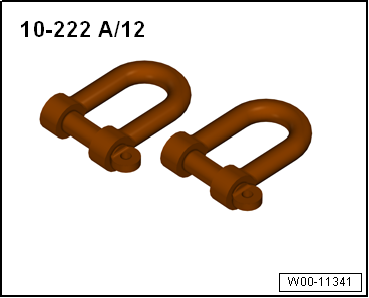
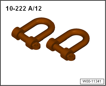
- Additional hook -10-222 A/12-
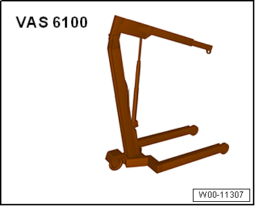
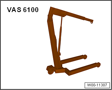
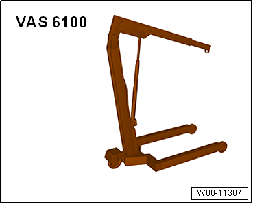
- Workshop crane -VAS 6100-
Work sequence
- Engine/transmission unit removed and mounted on engine holder -T10483-.
- Remove starter motor → Electrical system.
- Fit shackle -10-222A/12- to the transmission.
- Hook workshop crane -VAS 6100- onto shackle -10-222A/12-.

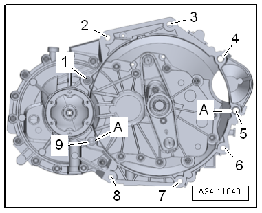
- Unscrew bolts -1, 2, 3- and -6... 9- of the connection on the engine.

Note
- Disregard items -4, 5- and -A-.
- Pull transmission off the engine.
Separating engine and transmission, vehicles with dual-clutch transmission
Required Special Tools, Test and Measuring Equipment and Auxiliary Items
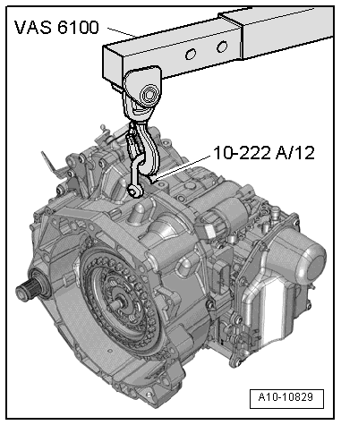
- Shackle -10 - 222 A /12-
- Workshop crane -VAS 6100-
Work sequence
- Engine/transmission unit removed and installed on engine holder -T10497-.
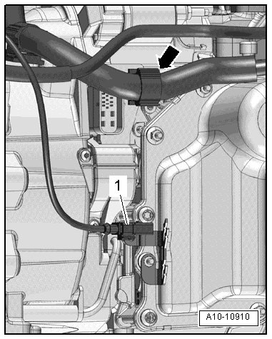
- Expose the electrical wiring harness -arrow-.

Note
-Item 1- can be disregarded.
- Remove starter motor → Electrical system.
- Attach the transmission to the workshop crane -VAS 6100- using shackle -10 - 222 A /12-.
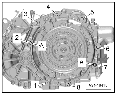
- Unscrew bolts -1 ... 8- of the transmission-to-engine connection.

Note
-Item A- can be disregarded.
- Pull transmission off the engine.
Secure engine to engine and transmission holder
Required Special Tools, Test and Measuring Equipment and Auxiliary Items
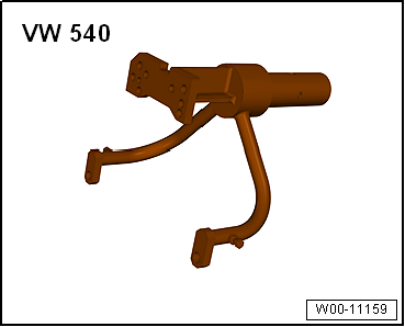
- Engine and transmission holder -VW 540-
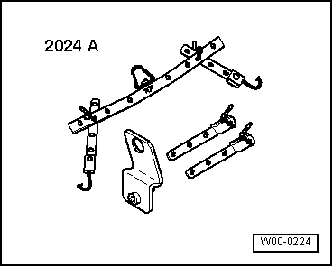
- Lifting fixture -2024 A-
- Engine and transmission holder -VAS 6095-

- Workshop crane -VAS 6100-
Work sequence
- Engine removed
- Transmission separated from engine "Separating engine and transmission".

Note
-Item 2- can be disregarded.
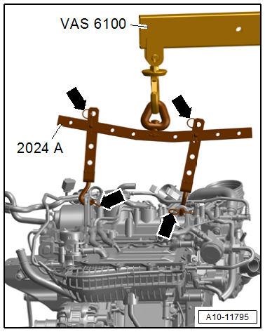
- Hook lifting fixture -2024 A- to the engine and to the workshop crane -VAS 6100-, as shown in the illustration.

Note
To match the center of gravity of the unit, the perforated rails must be inserted as shown in the illustration.
Risk of accident from loose lifting fixture parts. Hook receivers and locating pins on the lifting fixture must be secured with clip pins -arrows-.
- Lift the engine off the T10483 with the workshop crane -VAS 6100-.
- Secure the engine with the engine and transmission holder -VW 540- to the engine and transmission holder -VAS 6095-, as shown in the illustration.
- Insert spacer washers -arrow-.
- Dimension -a- = 10 mm.

Installing engine
Installation is carried out in the reverse order of removal, observing the following:
- Check clutch release bearing for wear, replace if necessary.
- Lightly lubricate the clutch release bearing, release bearing guide sleeve and input shaft splines with G 000 100.
- Check whether locating sleeves for centering engine/transmission are present in the cylinder block; install if necessary.
Transmission tightening torques.
Install starter → Electrical system.
- Align the engine mount without tension by rocking the engine.

Note
Tightening torques for unit mounting "Unit mounting".
Vehicles with air conditioning
- Install A/C compressor → Heating, air conditioning.
- Install serpentine belt "Removing and installing serpentine belt".
Continuation for all vehicles
- Install right and left driveshafts → Suspension, axles, steering.
- Install shift linkage on transmission.
- Top up coolant "Draining and topping up coolant".
- Install air filter housing "Removing and installing air filter housing".
- Connect the vehicle diagnostic tester.
- Delete adaptation values and adapt engine control module -J623- to throttle valve control unit → Vehicle diagnostic tester "Guided function".
- Perform vehicle system test → Vehicle diagnostic tester "Guided fault finding".
- End vehicle system test so that any fault memory entries caused by installation are deleted automatically.
Observe the safety measures applicable for a road test.
- Carry out road test.
- Repeat vehicle system test and rectify any faults that have occurred.