Controls
Remove and install light switch
Depending on equipment, the light switch -E1- contains the following components:
- Fog light and rear fog light switch -E23-
- Switch illumination bulb -L9-
Removing
- Switch off ignition and all electrical consumers and remove the ignition key.
- Turn the rotary knob of light switch -E1- to position "0".
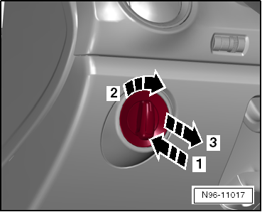
- Press the rotary knob of light switch -E1- in -1- and turn it slightly to the right -2-.
- Hold the rotary knob in this position and pull light switch -E1- out of the dash panel by the rotary knob -3-, taking into account the length of the connected cables.
- Unlock and disconnect the connector.
Installing
- Plug in the connector and lock it.
- Hold the light switch and press the rotary knob of light switch -E1- firmly in -1- and turn it slightly to the right -2-.
- Hold the rotary knob in this position and insert light switch -E1- into the dash panel -3-.
- Turn the rotary knob to position "0", release it and let light switch -E1- engage.

Remove and install headlight range control adjuster
Removing
- Switch off the ignition and all electrical consumers and remove the ignition key.
- Remove the footwell trim panel on the driver side → Body assembly work, interior.

Note
For clarity, the following illustration shows the installed headlight range control adjuster -E102- from the rear.
- Reach behind the dash panel and press together the two locking tabs -arrows- on headlight range control adjuster -E102-.
- Push headlight range control adjuster -E102- -2- inward out of the dash panel.
- Unlock and disconnect connector -1-.
Installing
Installation is carried out in the reverse order.

Remove and install center dash switch module
Depending on equipment, the following switches and lamps are combined in 2 switch modules and installed on the left and right of the heating/air conditioning controls. The switch modules are removed and installed in the same way; only one switch module is described. The removed switch modules cannot be disassembled further.
- Hazard warning light switch -E229-
- Passenger airbag OFF indicator lamp -K145-
- Rear window heating switch -E230-
- Right seat heating switch -E654-
- Left seat heating switch -E653-
- Start-stop operation switch -E693-
Required Special Tools, Test and Measuring Equipment and Auxiliary Items
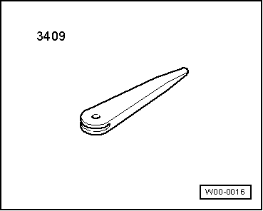
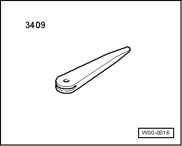
- Removal wedge -VAS 3409-

Note
- When removing and installing components in visible areas (switches, covers, trim panels, etc.), mask the areas where a lever tool (removal wedge -VAS 3409-, screwdriver) will be applied with commercially available adhesive tape.
- Both switch modules are removed and installed in the same way; only one switch module is described.
Removing
- Switch off ignition and all electrical consumers and remove the ignition key.
- Remove the center dash panel trim → Body assembly work, interior.
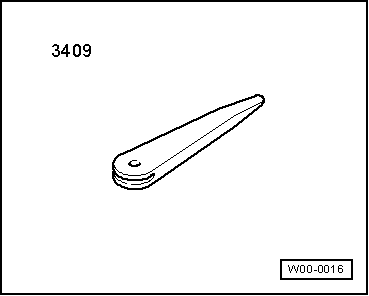
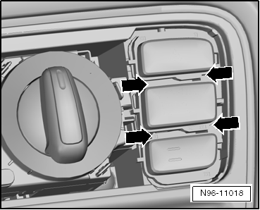
- Use removal wedge -VAS 3409- to pry the center dash switch module out at the latches -arrows-.
- Unlock and disconnect the connector, then remove the switch module.
Installing
Installation is carried out in the reverse order.
Remove and install start-stop operation switch
Start-stop operation switch -E693- is installed in the center dash switch module and cannot be replaced separately.
- Remove and install center dash switch module.
Remove and install hazard warning light switch
Hazard warning light switch -E229- is part of the center dash switch module and cannot be replaced separately.
Removing and installing center dash switch module.
Remove and install rear window heating switch
Rear window heating switch -E230- is part of the center dash switch module and cannot be replaced separately.
Removing and installing center dash switch module.
Remove and install seat heating switch
Right seat heating switch -E654- and left seat heating switch -E653- are part of the center dash switch module and cannot be replaced separately.
Removing and installing center dash switch module.
Remove and install passenger airbag deactivation key switch
Key switch for passenger airbag deactivation -E224- is installed in the side dash panel cover on the passenger side.

WARNING!
- Risk of airbag deployment!
- Improper handling of the airbag unit can cause the airbag to deploy.
- Observe the safety precautions when working on the airbag.

Note
When removing and installing components in the visible area (switches, covers, trim, etc.), mask the areas where a prying tool (removal wedge -VAS 3409-, screwdriver) will be applied with commercially available adhesive tape.
Required Special Tools, Test and Measuring Equipment and Auxiliary Items
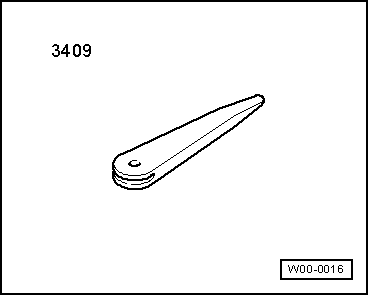
- Removal wedge -VAS 3409-
Removing
- Switch off ignition and all electrical consumers and remove the ignition key.
- Remove the side dash panel cover on the passenger side → Body assembly work, interior.
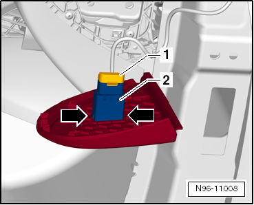
- Unlock connector -1- and disconnect it.
- Press the latches -arrows- on both sides and push key switch for passenger airbag deactivation -E224- -2- through the dash panel cover.
Installing
Installation is performed in the reverse order.
Remove and install window regulator control unit in driver door -E512-
Required Special Tools, Test and Measuring Equipment and Auxiliary Items
- Removal wedge -VAS 3409-
Depending on equipment, the window regulator control unit in driver door -E512- contains the following switches in the door trim:
Driver side:
- Front left window regulator switch -E40-
- Interior locking switch, driver side -E308-
- Mirror adjustment switch -E43-
Passenger side:
- Front right window regulator switch -E41-

Note
- To remove and install the interior locking switch, driver side -E308- and the mirror adjustment switch -E43-, the window regulator control unit in driver door -E512- on the driver side must first be removed.
- The front left window switch -E40- and front right window switch -E41- can be removed without first removing the window regulator control unit in driver door -E512-.
- When removing and installing components in visible areas (switches, covers, trim panels, etc.), mask the areas where a lever tool (removal wedge -VAS 3409-, screwdriver) will be applied with commercially available adhesive tape.
Removing
- Switch off ignition and all electrical consumers and remove the ignition key.
- Remove the driver side door trim panel → Body assembly work, interior.
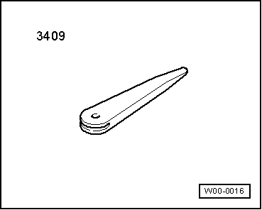
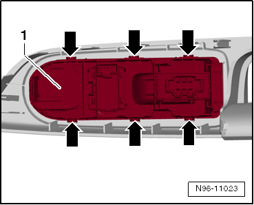
- Unlock the catches -arrows- of the window regulator control unit in driver door -E512--1- using removal wedge -VAS 3409- or a suitable screwdriver.
- Remove the driver side switch element -1- from the door trim panel, starting at the front.
Installing
Installation is carried out in the reverse order of removal, observing the following:
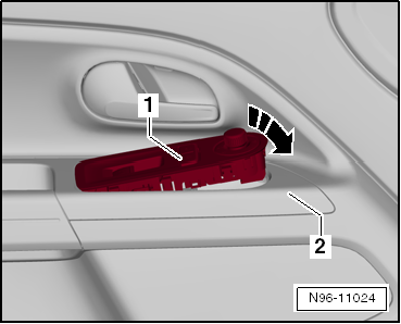
- Insert the driver side switch element -1- into the door trim panel -2- starting at the rear, then engage the front.
Removing and installing front window switch
Required Special Tools, Test and Measuring Equipment and Auxiliary Items
- Removal wedge -VAS 3409-

Note
- The following illustrations show the removal and installation of the front left window switch -E40-.
- Removal and installation of the front right window switch -E41- is carried out in the same way.
- To remove the front left window switch -E40-, it is not necessary to remove the window regulator control unit in driver door -E512-.
Removing
- Switch off ignition and all electrical consumers and remove the ignition key.
- Remove the front door trim panel → Body assembly work, interior.
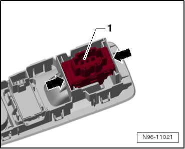
- Unlock the two catches -arrows- and remove the front left window switch -E40--1- from the window regulator control unit in driver door -E512-.
Installing
Installation is performed in the reverse order.
Removing and installing mirror adjustment switch -E43-/ -E168-
Required Special Tools, Test and Measuring Equipment and Auxiliary Items
- Removal wedge -VAS 3409-
Removing
- Remove the driver side switch element.

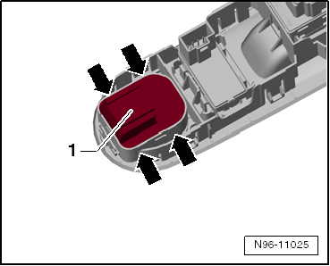
- Unlock the catches -arrows- and push the mirror adjustment switch -E43--1- out of the window regulator control unit in driver door -E512-.
Installing
Installation is performed in the reverse order.
Removing and installing driver side interior locking button
Required Special Tools, Test and Measuring Equipment and Auxiliary Items
- Removal wedge -VAS 3409-
Removing
- Remove the window regulator control unit in driver door -E512-.
- Unlock the catches -arrows- and push the driver side interior locking button -E308--1- out of the window regulator control unit in driver door -E512-.
Installing
Installation is performed in the reverse order.

Removing and installing center console switch module
The center console switch module -EX23- is installed in the center console in front of the gear lever and, depending on equipment, contains the following components:
- Tire pressure indicator button -E492-
- Emergency braking function button -E773-
Removing
- Switch off ignition and all electrical consumers and remove the ignition key.
- Remove the center console cover → Body assembly work, interior.
- Unlock the two locks -arrows- and swing the installation frame -1- outward out of the center console -2-.

- Unlock the catches -arrows- with a suitable screwdriver and push the center console switch module -EX23--1- out of the installation frame -2-.
Installing
Installation is carried out in the reverse order of removal, observing the following:
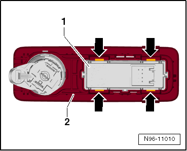
- Insert the installation frame -1- into the center console cover -2- on the right side first, then engage it on the left side.
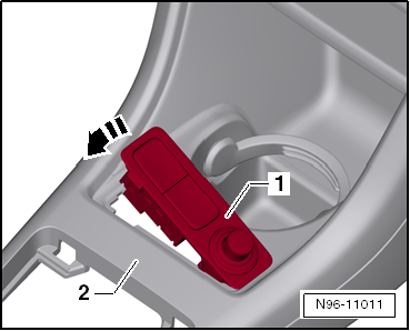
Removing and installing emergency braking function button
The emergency braking function button -E773- is part of the center console switch module -EX23- in the center console in front of the gear lever.
Remove and install center console switch module -EX23-.
Removing and installing sunroof adjustment control
Removing
- Switch off the ignition and all electrical consumers and remove the ignition key.
- Remove the front interior and reading lamp.
- Unlock the catches -arrows- and remove the sunroof adjustment -EX4--3- from the interior and reading light.
Installing
Installation is carried out in the reverse order.
